System Specifications
110118-0001A 57
6.3.2 LCD Display
LCD display panels have a wide range of voltage and data requirements. The BitsyXb has a
number of adjustable voltages to support these requirements, as well as controls for brightness
(backlight) and contrast (passive LCD panels). See section 4.5.5 for further details.
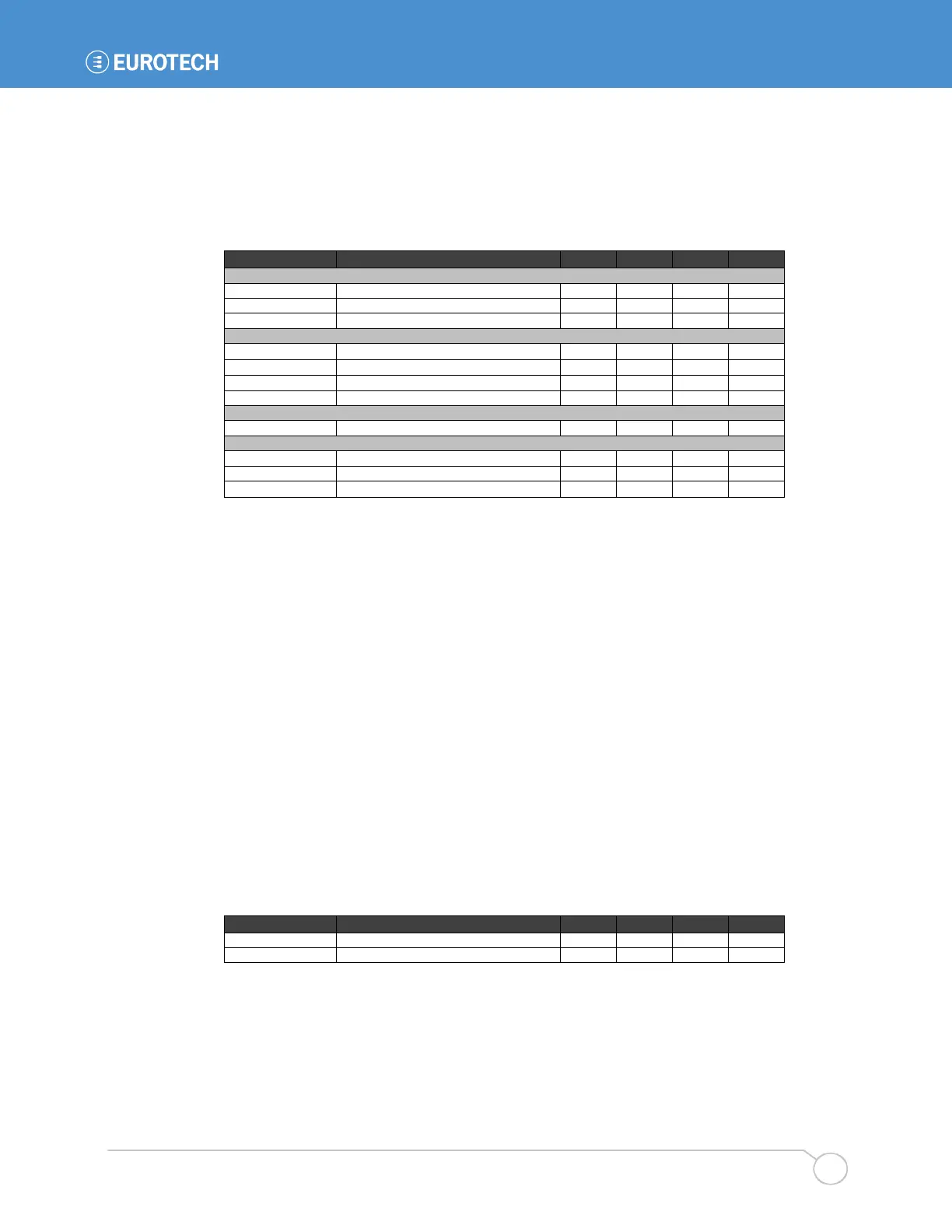
Display power supply (note 7)
P pnl_pwr Display power (note 8) 2 W
Panel data voltage (note 9)
Scan direction (active displays) (4.6.3)
kΩ
Contrast Control (passive LCD displays) (4.6.7)
Low-voltage contrast adjust (note 12)
Brightness Control (backlight, 4.6.6)
R backlightPWM PWM series resistance (note 14) 1.2
Ω
Notes:
7. JP2 selects the display voltage.
8. Total power available depends on system power budget.
9. Systems are configured at the factory with buffers for 3.3 or 5 V panel data. R148 selects
5 V power for the buffers while R137 selects 3.3 V power. 5 V displays with
Vih <= 0.6Vpnl_pwr (3.0 V) will work reliably with 3.3 V data.
10. PNL_RL is pulled up with R193 or pulled down with R207.
11. PNL_UD is pulled up with R191 or pulled down with R192.
12. Vcon is the low-voltage PWM signal used to control Vee. It can be used directly with some
passive displays to control contrast.
13. Backlight On is an open-collector output. Most backlight inverters include pull-up resistors
on their on/off inputs. The maximum voltage shown is the rating of the BitsyXb output
transistor.
14. The backlight on/off and PWM outputs are driven by the ADSmartIO controller
6.3.3 Touch Panel Controller
The BitsyXb uses touch panel controllers from Burr Brown. It uses the ADS7846 to support four-
wire analog-resistive touch panels and the ADS7845 to support five-wire panels. The system is
factory-configured for use with four-wire panels. All touch-panel signals are ESD and RF
protected. The touch panel controller is powered during sleep mode and can generate an interrupt
to wake the system.