Power and Power Management
110118-0001A 45
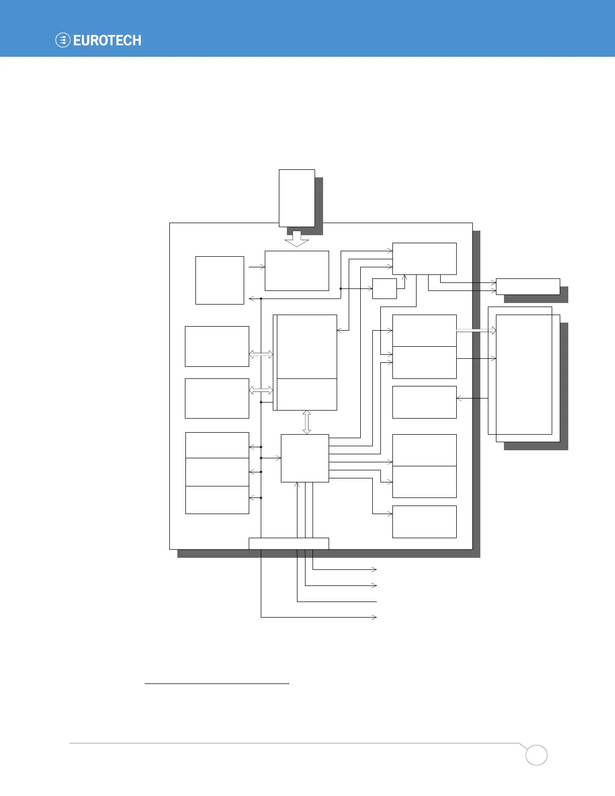
The following diagram illustrates the architecture of the BitsyXb power management system. At
the heart of the system is a power controller that controls the state of the various power
subsystems of the BitsyXb. Under control of the processor, this controller can manage most of the
power distribution of the board. The PowerEnable signal controls the rest of the subsystems.
19
In the diagram, the power management modes of each of the subsystems are indicated in gray.
Arrows indicate the direction of both signal flow and of power management.
BitsyXb
LCD Display
Backlight Inverter
PCMCIA and CF
Touch Screen
Contrast (Vee)
Display Power &
Data Signals
System
Controller
ON
Brightness PWM
On/Off
RS-232 Buffers
ON
POWER-DOWN
RUN
POWER-DOWN
ON
OFF
ON, OFF
3.3V
5V
OFF
PXA255 I/Os
ON
OFF
PXA255 Core
RUN
IDLE
SUSPEND
DRAM
RUN
SUSPEND/Self-
Refresh
Flash
READ/WRITE
STANDBY
POWER DOWN
Power Management Flow
ADSmartIO
RUN
SUSPEND
Touch Panel
AC97 Codec &
Mic Pre-amps
ON, OFF
Audio Amplifier
ON
POWER-DOWN
/CONN_PE1
CONN_PE2
RqOnOff
PowerEnable
Vcon
Vref
ON
OFF
Power Supply, 5V
RUN
BURST MODE
3.3V (Vddx)
RUN: Switcher
SUSPEND: Linear
Core Voltage
ON
OFF
J3
PC Card
System
Controller
ON
19
The controller inverts the PowerEnable signal for use with some subsystems. This detail is not
shown in the diagram.