EVCO S.p.A. EVlink Wi-Fi | Installer manual ver. 1.1 | Code 144IF25TWXE114
page 5 of 18
2 DESCRIPTION
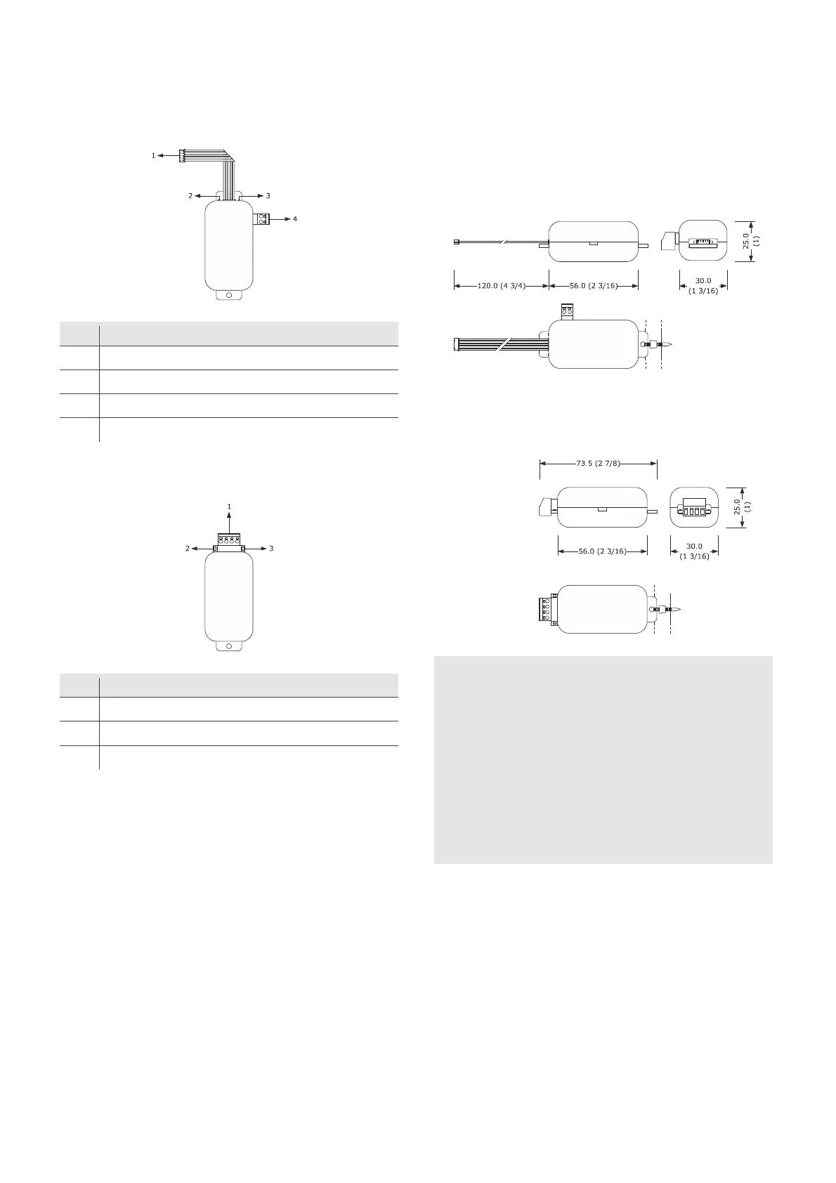
2.1 Description EVIF25TWX
Part Description
1 Pico-Blade connector (TTL MODBUS port)
2 Red LED (MODBUS communication status)
3 Green LED (Wi-Fi communication status)
4 Plug-in screw terminal block (independent power supply)
2.2 Description EVIF25SWX
Part Description
1 Plug-in screw terminal block (RS-485 MODBUS port)
2 Red LED (MODBUS communication status)
3 Green LED (Wi-Fi communication status)
3 MEASUREMENTS AND INSTALLATION
Measurements in mm (inches); to be fitted to a hard surface with a cable tie
(not provided).
3.1 Measurements and installation
EVIF25TWX
3.2 Measurements and installation
EVIF25SWX
INSTALLATION PRECAUTIONS
- Ensure that the working conditions are within the limits stated in
the TECHNICAL SPECIFICATIONS section
- Install the device where the Wi-Fi signal is strong
- Do not install the device close to metal parts which may impede
Wi-Fi communication
- Do not install the device close to heat sources, equipment with a
strong magnetic field, in places subject to direct sunlight, rain,
damp, excessive dust, mechanical vibrations or shocks
- In compliance with safety regulations, the device must be installed
properly to ensure adequate protection from contact with electrical
parts. All protective parts must be fixed in such a way as to need
the aid of a tool to remove them