EVCO S.p.A. EVlink Wi-Fi | Installer manual ver. 1.1 | Code 144IF25TWXE114
page 7 of 18
1. Connect the TTL MODBUS port on the EVlink Wi-Fi to the TTL
MODBUS port on the controller.
2. 2.1 Connect the end of an independent power supply cable to
terminal 1 of the plug-in screw terminal block on EVlink Wi-
Fi.
2.2 Connect the end of the other independent power supply
cable to terminal 2 of the plug-in screw terminal block on
EVlink Wi-Fi.
Before powering up the controller and EVlink Wi-Fi, see the section FIRST-TIME
USE.
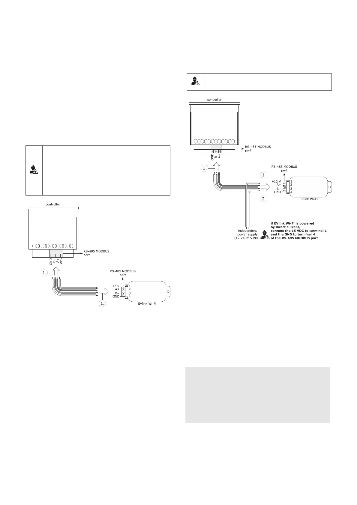
4.4 Electrical connection of EVIF25SWX
to a controller able to power EVlink
Wi-Fi
N.B.
- Connect the RS-485 using a twisted pair
- The maximum permitted length of the RS-485 connection cables
is 1000 m (3280 ft) and enables EVlink Wi-Fi to be installed in
the most convenient place. Make sure that the voltage supplied
to EVlink Wi-Fi is within the limits set in the section TECHNICAL
SPECIFICATIONS
1. 1.1 Connect terminal 4 of the EVlink Wi-Fi RS-485 MODBUS
(GND) port to the GND terminal of the RS-485 MODBUS
port of the controller.
1.2 Connect terminal 3 of the EVlink Wi-Fi RS-485 MODBUS (B-)
port to the B- terminal of the RS-485 MODBUS port of the
controller.
1.3 Connect terminal 2 of the EVlink Wi-Fi RS-485 MODBUS
(A+) port to the A+ terminal of the RS-485 MODBUS port of
the controller.
1.4 Connect terminal 1 of the EVlink Wi-Fi RS-485 MODBUS
(+12 V) port to a terminal on the controller that is able to
supply 12 VAC/15 VDC (VPS).
Before powering up the controller and EVlink Wi-Fi, see the section FIRST-TIME
USE.
4.5 Electrical connection of EVIF25SWX
to a controller unable to power
EVlink Wi-Fi
N.B.
Connect the RS-485 using a twisted pair
1. 1.1 Connect terminal 4 of the EVlink Wi-Fi RS-485 MODBUS
(GND) port to the GND terminal of the RS-485 MODBUS
port of the controller.
1.2 Connect terminal 3 of the EVlink Wi-Fi RS-485 MODBUS (B-)
port to the B- terminal of the RS-485 MODBUS port of the
controller.
1.3 Connect terminal 2 of the EVlink Wi-Fi RS-485 MODBUS
(A+) port to the A+ terminal of the RS-485 MODBUS port of
the controller.
2. 2.1 Connect terminal 4 of the EVlink Wi-Fi RS-485 MODBUS
(GND) port to the end of an independent power supply
cable.
2.2 Connect terminal 1 of the EVlink Wi-Fi RS-485 MODBUS
(+12 V) port to the end of the other independent power
supply cable.
Before powering up the controller and EVlink Wi-Fi, see the section FIRST-TIME
USE.
PRECAUTIONS FOR ELECTRICAL CONNECTION
- If the device is moved from a cold to a warm place, humidity may
cause condensation to form inside. Wait for about an hour before
connecting it to the controller or the independent power supply
- Disconnect the device from the controller or the independent power
supply before carrying out any type of maintenance
- For repairs and for further information, contact the EVCO sales
network