58
Electrical System
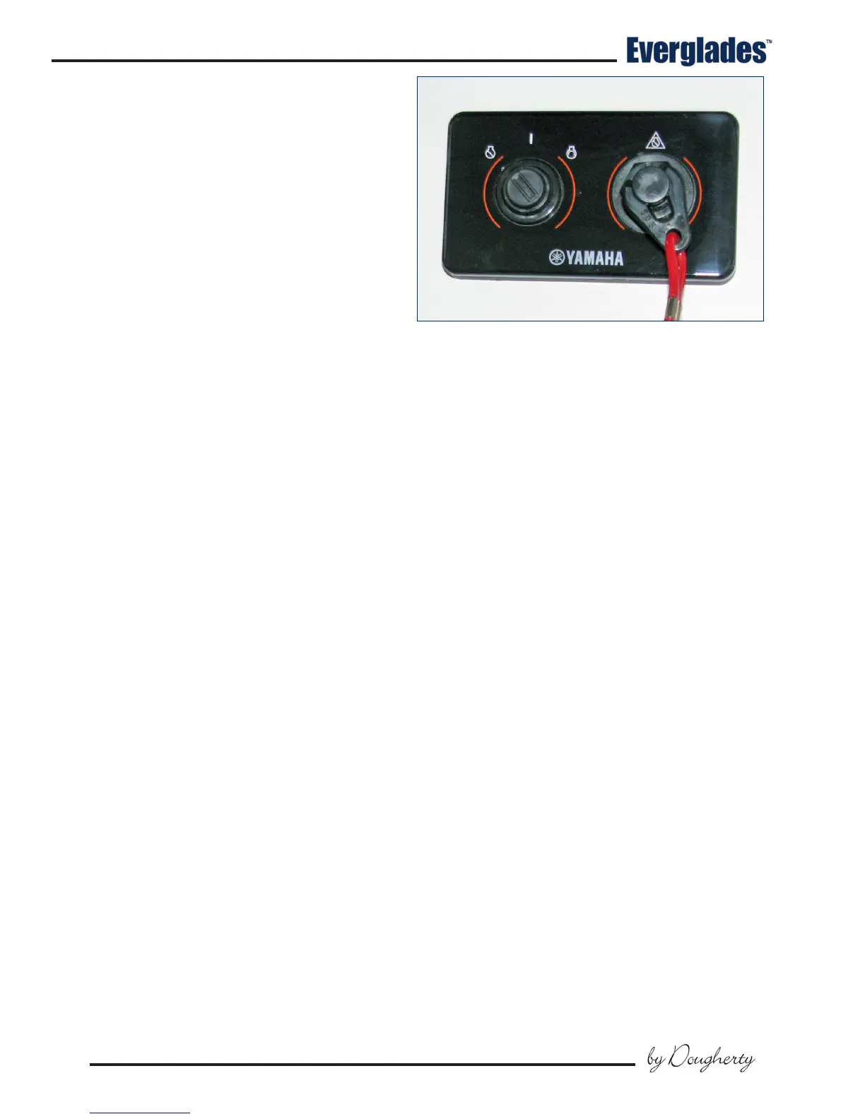
Typical Yamaha Command Link Ignition
6.5 Ignition Switch Panels
Ignition Switch Panels
Ignition switch panels are unique to each engine
manufacturer and the engine control options
selected. Your dealer will provide you with the
proper starting procedure for your boat at the time
of delivery. Additional information for the ignition
switch system installed in your boat is located in
the engine and control system operating manuals
included in your information packet.
Single Engine Yamaha Command Plus
®
Link Ignition
Most single engine Everglades boats are equipped
with a Yamaha engine and Command Link or Com-
mand Link Plus
®
ignition key panels that oer the
latest in technology and durability.
The ignition switch is a key activated switch, lo-
cated near the helm below the steering wheel,
which starts and stops the engine. The switch
has OFF - ON and momentary START positions.
Starting procedure
Make sure the engine is down with the shift lever in
the neutral position and your hand on the control
lever. Turn the ignition key to the ON position to
activate the fuel pump and ignition system. Wait
5 seconds for the fuel pump to pressurize the sys-
tem, then turn the key to the start position. When
the engine starts, release the key and the switch
will automatically go to the run position. Stop
the engine by turning the key to the OFF position.
The engine ignition circuits are protected by fuses
or circuit breakers located on each engine.
6.6 12 volt Accessory Switch Panels
The main accessory switch panel is located at the
helm. Most of the circuit breakers that protect the
accessories activated by the switches are located
in the head compartment breaker panel.
The switch panels are equipped with push button
switches that are labeled for the accessories they
control. An LED light built into most switches indi-
cates that the circuit is activated.
The following is a description of the accesso-
ries controlled by the main accessory switch
panel:
Horn
A momentary switch that activates the boat horn.
Nav/Anc
Press the switch once to activate the navigation
lights. Press the switch again for anchor light
only. Press the switch again to turn the lights o.
Bilge 1
Press the switch once to manually activate the aft
bilge pump located in the stern bilge near the tran-
som. Press the switch again to turn the pump o.
The pump moves water out through a tting in the
hull. The pump is also activated by an automatic
oat switch that is activated whenever the batter-
ies are connected. This pump will run as needed
whenever the water in the bilge accumulates high
enough to raise the oat switch to the ON position
and turn o when the water is removed.
Bilge 2
Press the switch once to manually activate the aft
bilge pump located in the stern bilge just forward
of the aft bilge pump. Press the switch again to
turn the pump o. The pump moves water out
through a tting in the hull. The pump is also
activated by an automatic oat switch that is
activated whenever the batteries are connected.
This pump will run as needed whenever the water
in the bilge accumulates high enough to raise the
oat switch to the ON position and turn o when
the water is removed.
Notice:
The bilge pumps will start automatically
when there is sucient water in the bilge to
activate the oat switch. Each oat switch is
protected by a fuse located in the aft system
compartment and is always supplied current
when the batteries are connected.