Do you have a question about the Everlast CYCLONE 140E and is the answer not in the manual?
Explains warranty coverage and policies for USA and Canada, directing users to specific web links for full details.
Provides phone numbers and email addresses for US technical support, welding support, and sales.
Provides phone numbers and email addresses for Canadian technical support and sales.
Guides users in other regions on how to find relevant contact details via the website or US office.
Warns about High Frequency energy interfering with pacemakers and advises consulting a physician.
Emphasizes using safety glasses, welding helmets, and protective clothing to prevent eye damage and injury.
Details risks of electrocution, keeping equipment dry, avoiding wet areas, and fire prevention measures.
Provides guidelines for safely handling, storing, and transporting gas cylinders, including capping and checking for leaks.
Discusses inhalation hazards from welding fumes, toxic gases, and the need for adequate ventilation and medical advice.
Warns against using chlorinated solvents like brake cleaner due to the risk of producing lethal phosgene gas.
Reaffirms pacemaker warnings, detailing risks from High Frequency and electromagnetic fields during welding.
Stresses the importance of keeping all safety guards and shields in place and not modifying them.
Covers awareness of trip hazards and precautions for handling hot metal after welding.
Details protection needed from UV radiation and precautions regarding electromagnetic fields.
Advises on keeping the work area clear of unauthorized persons, pets, and children.
Specifies requirements for generator power output, THD, and types of generators to use or avoid.
Provides guidelines on starting/stopping generators, ECO mode, and RPM management.
Recommends specific gauge and maximum length for extension cords to ensure safe operation.
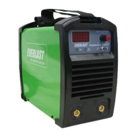
Lists detailed technical specifications of the welder, including voltage, current, duty cycle, dimensions, and more.
Explains how duty cycle is measured, factors affecting it, and the unit's thermal protection mechanism.
Details electrical requirements, NEC guidelines, and recommendations for proper breaker and wire sizing.
Defines duty cycle, explains the unit's heat sensor, and how to manage over-temperature conditions.
Warns that repeatedly triggering duty cycle protection can shorten the unit's lifespan and weaken components.
Guides users on how to unpack the welder, inspect contents, and report any issues within 72 hours.
Provides instructions on how to test for gas leaks using soapy water or leak solution.
Advises on positioning the welder away from the work area to prevent turbulence and ensuring adequate cooling space.
Emphasizes consulting electricians and following NEC codes for dedicated 120V circuits for welders.
Details recommended extension cord gauge and length limitations for safe and proper welder operation.
Explains gas options for MIG (GMAW) and notes that flux-cored wire is gasless.
Details steps for connecting the regulator to the cylinder and the unit, including checking fittings.
Guides on setting the gas flow rate using the regulator adjustment knob and checking the flow meter.
Explains how to adjust gas flow for different conditions and when to replace cylinders.
Warns about properly closing the main cylinder valve when not in use to prevent gas accumulation.
Guides on installing the MIG gun, connecting it, and testing wire feed operation.
Explains how to select the correct polarity for MIG (Gas) and Flux-Cored (Gasless) welding processes.
Details the correct assembly and installation of the wire spool, including collar orientation.
Illustrates the correct direction of wire unwrapping and spool rotation for proper feeding.
Discusses the SM100N spool gun for extended reach, especially for Aluminum and Stainless.
Explains how to identify, select, and change drive rolls based on wire size and type.
Provides instructions on feeding the wire from the spool through the feeder mechanism and MIG gun.
Details the process of assembling the MIG gun components and installing the wire.
Instructs on trimming the wire to the correct length (1/4"-3/8") for optimal arc starts.
Explains how to adjust drive roll tension for proper wire feeding, using a wood block test.
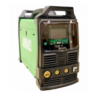
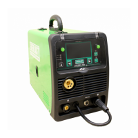
Identifies and explains the function of each numbered component on the front panel of the welder.
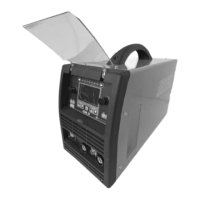
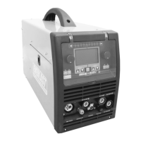
Identifies and explains the function of each numbered component on the rear panel of the welder.
Identifies and explains the purpose of each control and display on the welder's front panel.
Explains how to operate the welder in manual mode, adjusting wire feed speed and voltage.
Compares Manual and PowerSet modes, guiding users on which mode to choose based on experience.
Guides users on selecting gas type, wire diameter, and metal thickness for automatic setting generation.
Explains what PowerSet mode is and how it simplifies setting selection for users.
Explains reasons why certain settings might be unavailable or blocked in PowerSet mode.
Details which metals are supported by PowerSet and discusses its operational limitations.
Provides a chart of recommended Wire Feed Speed (WFS) and Voltage ranges for various gas types, wire sizes, and metal thicknesses.
Explains the role of voltage in weld bead profile and wire feed speed in controlling amperage and penetration.
Guides on the initial steps for starting an arc, including trimming wire and gun positioning.
Discusses the effects of pushing or pulling the gun and proper angle for different welding scenarios.
Emphasizes the importance of cleaning metal surfaces for sound welds, especially for MIG and TIG.
Advises on using multiple passes for thicker materials and the benefits for weld quality.
Details when to use multiple passes for welds over 1/4 inch thickness and the benefits.
Describes various weld joint types (V-groove, U-groove, etc.) and preparation methods for best results.
Explains the correct gun angles (push, drag, vertical) for different welding processes and materials.
Lists common error codes displayed by the unit and provides corresponding diagnostic information and solutions.
Provides a table of common welding issues, their possible causes, and recommended solutions.
| Input Voltage | 120V |
|---|---|
| Input Phase | Single Phase |
| Welding Processes | Stick (SMAW), TIG (GTAW) |
| Amperage Range | 10-140A |
| Duty Cycle @ 140A | 30% |
| Electrode Size Range | 1/16" |