EasyManua.ls Logo

Everlast Cyclone 200E - User Manual

Everlast Cyclone 200E
33 pages
Print Icon
To Next Page IconTo Next Page
Loading...
Operators Manual
Publish Date: APRIL 2021
EVCY200E2021 Rev. 1
USA/North America
©Everlast Power Equipment
GMAW
FCAW
120/240V
1 Phase
Welders, Plasma Cutters, Multi-Process
Safety, Setup and General Use Guide
FUNCTION: 200A MIG Welder with PowerSet Mode
PURCHASE DATE:
WELDER SERIAL NUMBER:
OPTIONAL ACCESSORY SERIAL NUMBER:
MIG
Flux-Cored
Spool-Gun
Question and Answer IconNeed help?

Do you have a question about the Everlast Cyclone 200E and is the answer not in the manual?

Summary

Initial Operator Actions and Warranty

Product Registration and Warranty Claim Process

Guidance on registering the product and initiating a warranty claim.

Support, Warranty, and Contact Details

Everlast Contact Information Directory

Listing of contact details for technical, sales, and support teams across regions.

Safety Warnings and Precautions

Electrical Safety, Fire Prevention, and Gas Cylinders

Addresses risks of shock, fire hazards, grounding, and safe handling of gas cylinders.

Health and Environmental Safety Warnings

Generator and Extension Cord Guidelines

Generator Operation Requirements

Rules for operating the welder with generators, including clean power and avoiding ECO mode.

Technical Specifications and Electrical Setup

Welder Product Specifications

Detailed technical data including voltage, current, duty cycle, and physical dimensions.

Duty Cycle and Cooling Procedures

Explanation of duty cycle limits and recommended methods for cooling the unit.

Circuit Breaker and Wiring Recommendations

Advice on selecting correct circuit breakers and wire sizes per electrical codes.

Detailed Duty Cycle Explanation

Understanding Welder Duty Cycle Operation

Comprehensive explanation of duty cycle, its relation to temperature, and cooling protocols.

Welder Setup: Power Connections

Connecting to 240 V and 120 V Power Sources

Instructions for connecting the welder to different voltage power outlets.

Selecting Appropriate Breaker and Wire Gauge

Guidance on choosing correct circuit protection and wire size for the welder's power requirements.

Welder Setup: Shielding Gas System

Welder Setup: Regulator Flow Adjustment

Welder Setup: Wire Feed and Polarity

MIG Gun Installation and Wire Feed Testing

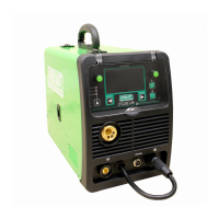
Procedures for installing the MIG gun and verifying the wire feeding mechanism.

Polarity Selection for Welding Processes

Guidance on choosing correct polarity for MIG and Flux-Cored welding to ensure weld quality.

Welder Setup: Wire Spool Management

Welder Setup: Drive Rolls and Wire Threading

Drive Roll Identification and Replacement

How to identify, select, and change drive rolls for different wire sizes and types.

Welder Setup: Wire Tensioning

Component Identification: Front Panel

Front Panel Components Overview

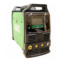
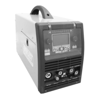
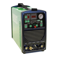
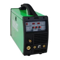
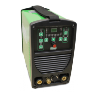
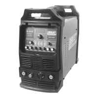
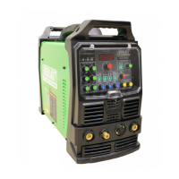
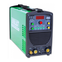
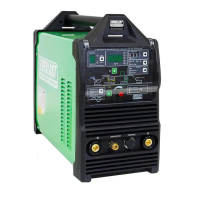
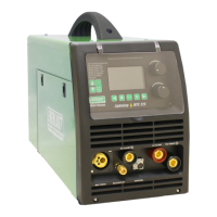
Identification and explanation of all components located on the welder's front panel.

Component Identification: Rear Panel

Rear Panel Components Overview

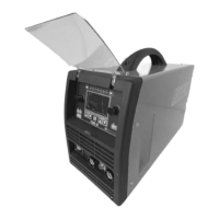
Identification and explanation of all components located on the welder's rear panel.

Component Identification: Control Panel

Control Panel Layout and Button Functions

Explanation of the control panel's layout, buttons, knobs, and their primary functions.

Control Panel Operation: Manual Mode

Control Panel Operation: PowerSet Mode

Welding Information and Techniques

Welding Techniques and Material Preparation

Welding Techniques: Push vs. Drag Angle

Troubleshooting: Error Codes

Diagnosing and Resolving Error Codes

Identification of common error codes, their diagnostic meanings, and resolution steps.

Troubleshooting: Common Welding Issues

Resolving Common Welding Problems

Listing of frequent welding issues, their causes, and recommended solutions.

Everlast Cyclone 200E Specifications

General IconGeneral
Duty Cycle60% at 200A
TIG Lift StartYes
Thermal Overload ProtectionYes
Welding ProcessesStick
Input PhaseSingle Phase
Stick Electrode SizeUp to 5/32 inch
TIG Electrode SizeUp to 3/32" (2.4mm)
Cooling SystemFan Cooled

Related product manuals