15
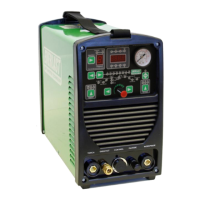
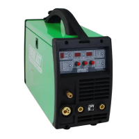
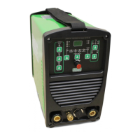
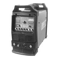
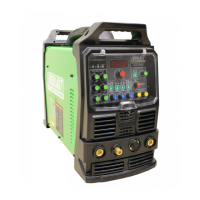
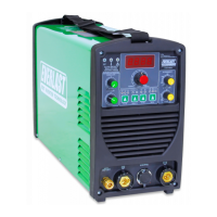
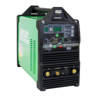
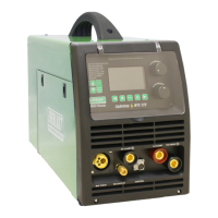
Setup Guide
Getting Started
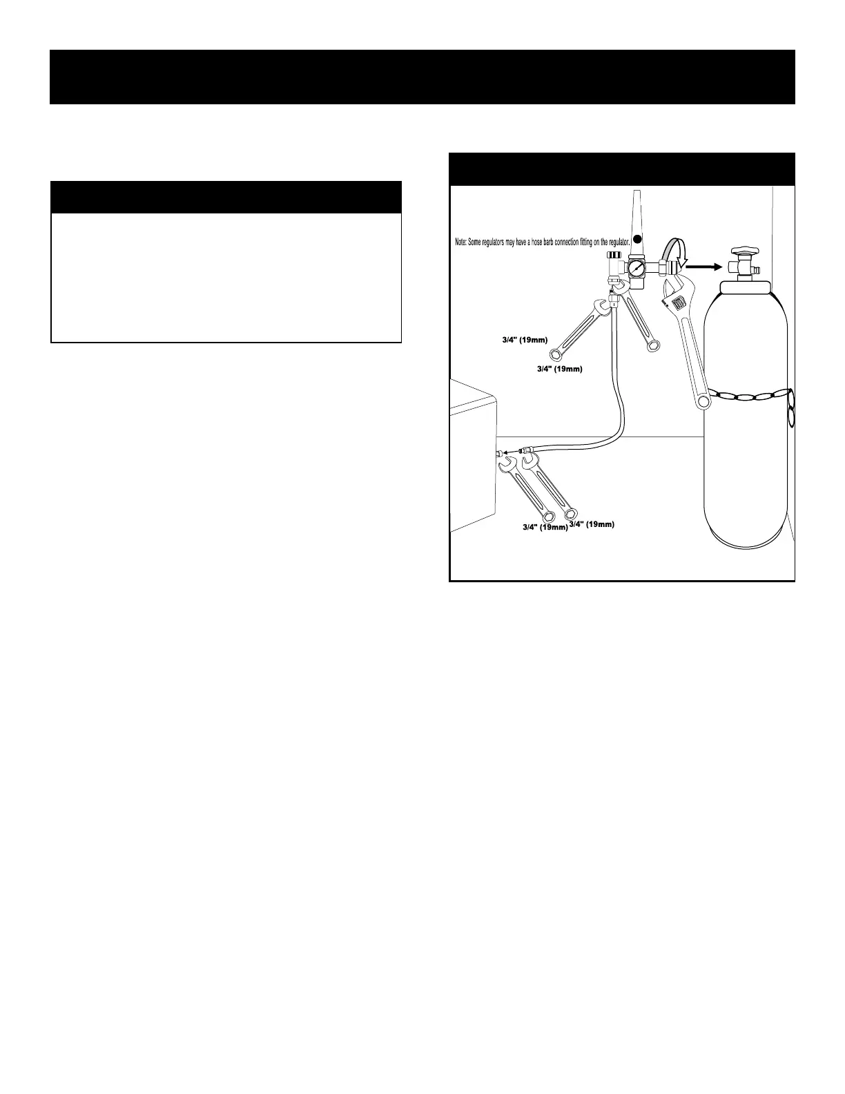
CONNECT YOUR UNIT TO THE SHIELDING GAS.
Always wear safety glasses when changing a cylinder. Before installing any
cylinder, the cylinder must be chained upright to the wall or a cart. After
installing the chains, uncap the cylinder. The cap may need a wrench or
screw driver inserted into the cap slot to break it loose. Stand to the side
of the valve, away from the discharge, and quickly open the cylinder to
give it a quick blast. This will dislodge any dirt or particles stuck in the
valve or the connection seat. This will help reduce the chance of dirt parti-
cles making its way into the solenoid valve, causing sticking issues later
on.
Connecting your cylinder will require a cylinder wrench(1 1/16”)to connect
the regulator to the cylinder (North American Cylinders with a 580 CGA
valve). If you do not have a cylinder wrench, an adjustable type wrench
will work, but make sure it is properly adjusted to prevent rounding of the
tting shoulders. Do not use pliers, or a serrated jaw wrench such as a
pipe wrench or basin wrench to tighten the tting. The design of the tting
means that no thread sealing tape or compound needs to be used.
Locate the Regulator in the packaging. The regulator may have either a
hose barb connection, or a threaded connection. If the regulator supplied
has a hose barb, make sure the hose barb tting is tight on the regulator.
Connect the regulator tubing to the regulator. Tighten with a 3/4” (19mm)
wrench. If it is a threaded connection, use two 3/4” (19mm) wrenches to
hold both the regulator and the tubing connection at the same time. Hold
counter pressure on the regulator connector while tightening the hose
tting to prevent damage to the regulator and to ensure maximum sealing.
After connecting the tubing to the regulator, connect the other end of the
tubing to the 5/8” CGA tting on the unit. Hold the tting on the unit with
one 3/4” (19mm) wrench rmly while tightening the hose tting with an-
other 3/4”(19mm) wrench.
• Important! Do not use thread tape or pipe sealant on any cylinder,
regulator or unit connection. The residue and debris may get into the
gas solenoid. Install the cylinder on the cart or chain it to the wall
closest to the welder. Do not overtighten. If leaks persist, remove
regulator from cylinder and inspect ttings for dirt or debris. Do not
attempt to repair a leaking regulator. Contact Everlast for a warranty
replacement if a leak is discovered in the regulator itself.
• Use a mixture of warm mildly soapy water to brush on the ttings and
check for leaks. Leaks are indicated by the forming of bubbles. Re-
tighten as needed. However, do not over-tighten. If the leak does
not disappear, remove the problem tting and inspect it for dirt or
metal lings, then re-install and recheck.
• Inspect and verify the pressure on the cylinder. The dial reads in
both PSI and Metric Equivalents.
ADJUST THE REGULATOR FLOW RATE.
• Switch the unit on. While holding the MIG gun trigger, start opening
the the regulator valve by twisting the regulator adjustment knob
counter clockwise As you open the valve, the floating ball will begin
to rise. NOTICE: To avoid spooling out and wasting wire during this
time, release the tension on the drive wheels by flipping the tension-
ing lever to the down position before you begin. This will release
tension and allow the drive rolls to safely turn without feeding any
wire.
• Increase the gas flow rate to a beginning point of 20-25 Cubic Feet
Per Hour (indicated on the clear gauge with the floating ball by CFH).
If MIG/Spool Gun welding Aluminum, increase flow rate to 35 CFH.
Read the middle of the ball for the best reading. Do not confuse
pressure on the cylinder gauge with the flow rate on the floating ball
gauge. Pressure present on the cylinder gauge does not mean gas is
flowing. However, a lack of pressure on the gauge may mean there
What Shielding Gas Should Be Used?
With this unit, the choice of shielding gas is simple. For MIG
(GMAW) you may choose either the standard 75/25 ( which is 75%
CO2 and 25% Argon), or you may choose 100% CO2. For Stainless,
use a Tri-MIX type of gas with Helium. For Self-Shielded Flux-Cored
wire welding, since it is gasless, no shielding gas is needed. Keep in
mind this unit is not designed for gas shielded Flux-Cored wire and
should not be used with this unit.
Connect Regulator To Cylinder And Unit.
 Loading...