205
POWERHEAD
POWERHEAD DISASSEMBLY
11
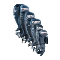
Remove the ball, guide, and spring of the shift
detent assembly from the crankcase.
Crankcase Disassembly
Remove screws, double-ended stud, and exhaust
side water cover.
Use a 1/8 in. diameter pin punch to push crank-
case taper pin toward the front side of the engine.
IMPORTANT: Do not use a tapered punch or
any other tool that could jam in or damage the
taper bore when removing the pin.
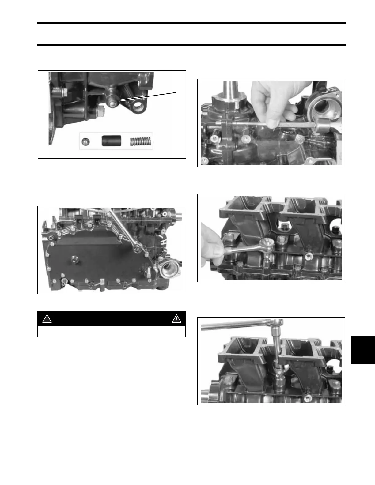
Remove crankcase flange screws.
Loosen in stages and remove the main bearing
nuts and washers.
1. Shift detent assembly 002135
002124
WARNING
Wear safety glasses to avoid injury.
1
002136
002137
002138
 Loading...