www.evolutionfury.com
22
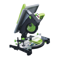
FENCE ASSEMBLY (Fig. 19)
The Fence Assembly consists of two (2)
main parts:
• TheAngleGauge.
• TheRipFenceFacePlate.
NOTE: The ‘T’ slot in the Rip Fence Face
Plate is not centrally located.
• SlidetheRipFenceFacePlateontothe
two (2) mounting screws found on the
Angle Plate.
• Ensurethatthewider(20mm)portionof
the Fence Face is downwards and will lie
on the saw table when in use.
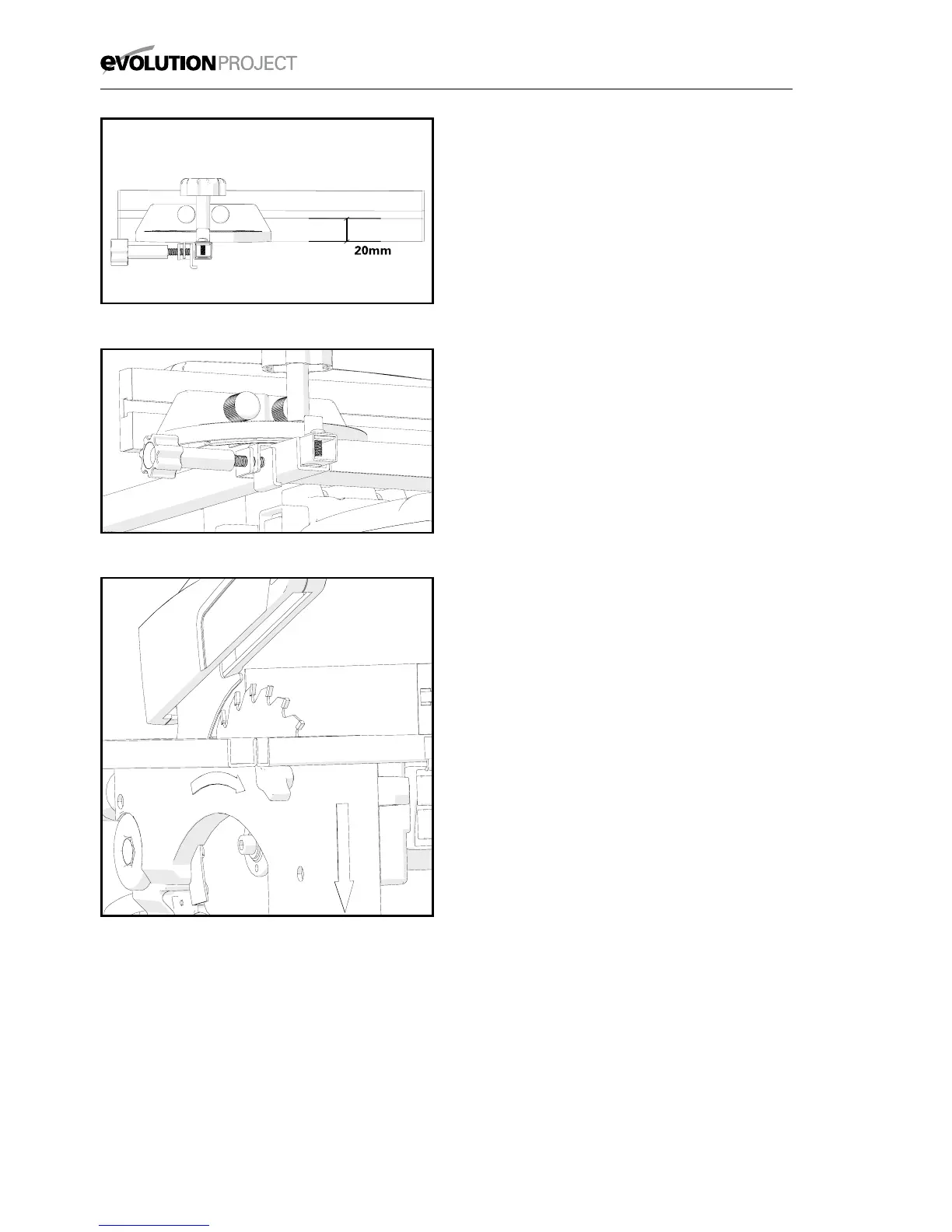
The Angle Plate can now be slid into the
Rip Fence channel found at the front of the
machine table. (Fig. 20)
Slide in from the Right Hand side ensuring
that the Locking Clamp engages correctly
with the front face of the Rip Fence channel.
FENCE ASSEMBLY AS A RIP FENCE
To use the Fence Assembly as a Rip Fence
the Face Plate must be accurately aligned
with the blade.
WARNING: Only carry out this procedure
with the machine disconnected from the
power supply.
To Align the Rip Fence:
• Ensurethatthetableisatitslowest
setting (see Fig. 23a &23b)
• SettheAngleGaugetoanindicated90
0
.
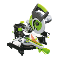
• SlidetheFenceAssemblyuptotheblade,
raising the Blade Guard by hand so that the
Face Plate rests alongside the blade and
underneath the Blade Guard. (Fig.21)
Gently tighten the Angle Gauge Locking
Clamp Screw to lock the Assembly into
the Rip Fence channel.
• CheckthattheFacePlateisinexact
alignment with the blade.
• Ifadjustmentisrequired,loosenslightly
the Angle Clamping Screw and adjust
the Angle Gauge until exact alignment is
achieved.
Fig. 21
Fig. 20
Fig. 19
height