OmniCure® SC- Series
UV Curing Solutions
www.excelitas.com/omnicure
Excelitas Canada Inc. 2021
All rights reserved
035-xxxxxR, rev.1
035-00539R rev 2
035-xxxxxR, rev.1
4
035-00539R rev 5
4 Connecting the System Controller
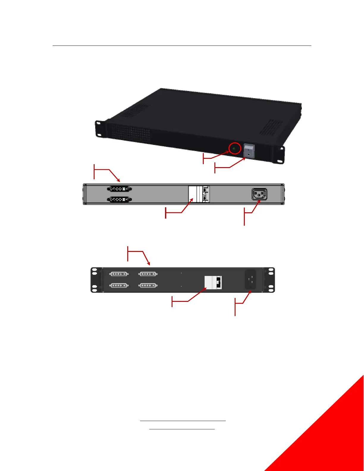
Figure 1 SC0750/SC1000/SC2000 Unit
Figure 2 SC3000 Unit
1. Before any electrical connections are made, ensure that the electrical circuit breaker is tripped. This can
be done by pushing the breaker switch away from the AC-inlet receptacle.
2. Ensure that the power switch on the front of the System Controller is set to the “off” position.
3. Locate the AC power cord and insert into the AC-inlet receptacle on the rear of the System Controller.
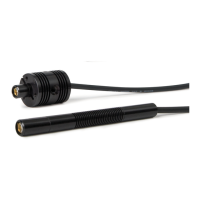
4. Locate the pair of 5W5 DC power connectors on the rear of the System Controller. Connect the DC
cable and tighten the jack screws to prevent the connector disengaging during use.
5. Connect the other end of the cable to the UV LED head and tighten the jack screws as before.
6. Connect any other control cabling to the UV LED head as required and as per the specific product
manual for that system.
Breaker Switch
AC Inlet Receptacle
DC Power
DC Power
AC Inlet R
Breaker Switch
 Loading...