Maintenance
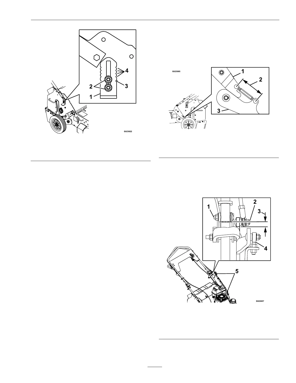
Figure14
1.Wheelstop3.Indicatorhole
2.Nuts4.Indicatornotches
4.Lowerthewheelstoptoreducethedepth.Raise
ittoincreasethecoringdepthandasrequired.
Note:Toensurethatthetinespenetratefully
intothesoil,weightscanbeaddedtotheback
ofthemachine.Themachinehasthreeweight
pocketsthatholdtheweights.Whenplacing
weight,ensurethattheloadisbalanced;ifusing
onlyoneweight,placeitinthecenterpocketand
ifusingtwo,placetheminthesidepockets.
Note:Theremovableweightsareheavy.Use
carewhenliftingthem.Makesurethatyoucan
holdthemsecurelybeforeliftingthem.Use
cautionwhenpositioningyourhandssothatyou
DoNotsetthemdownonyourhandsorngers.
5.Tightenthenutssecurelytolockthewheelstop
inplace.
6.Repeatsteps3through5forthewheelstop
ontheleftsideofthemachine.Usethevisual
indicatornotchesinthewheelstopandindicator
holesintheframetosetthewheelstopstothe
sameheightoneachside(seeFigure14).
AdjustingtheTineGround
EngagementLever
1.Stopengine,waitforallmovingpartstostop.
2.Disconnectthewirefromthesparkplug.
3.Raisethetinestothetransportposition.
4.Thewheelarmandthepivotshaftassembly
shouldhavesurface-to-surfacecontact.Ifnot,
checkthedistanceofthelowerliftlinkageand
adjustifnecessary.
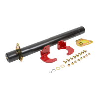
Figure15
1.Pivotshaftassembly
3.Wheelarmassembly
2.4.8inches(12cm)
5.Thelowerballjointbolt,ontheupperlinkrod,
shouldbeoffset1/4inch(6mm)fromthehandle
pivotbolt.Ifnot,loosenthelocknutsonthe
liftlinkstrapballjoints,adjustasnecessary,and
retightenlocknuts.
Figure16
1.Handlepivotbolt
4.Liftlinkstrapballjoint
2.Lowerballjointbolt5.Adjusthere
3.1/4inch(6mm)
6.Slidetheovallockingringsupwardonthehandle
andfoldthehandletowardstheengine.
27