- 15 -
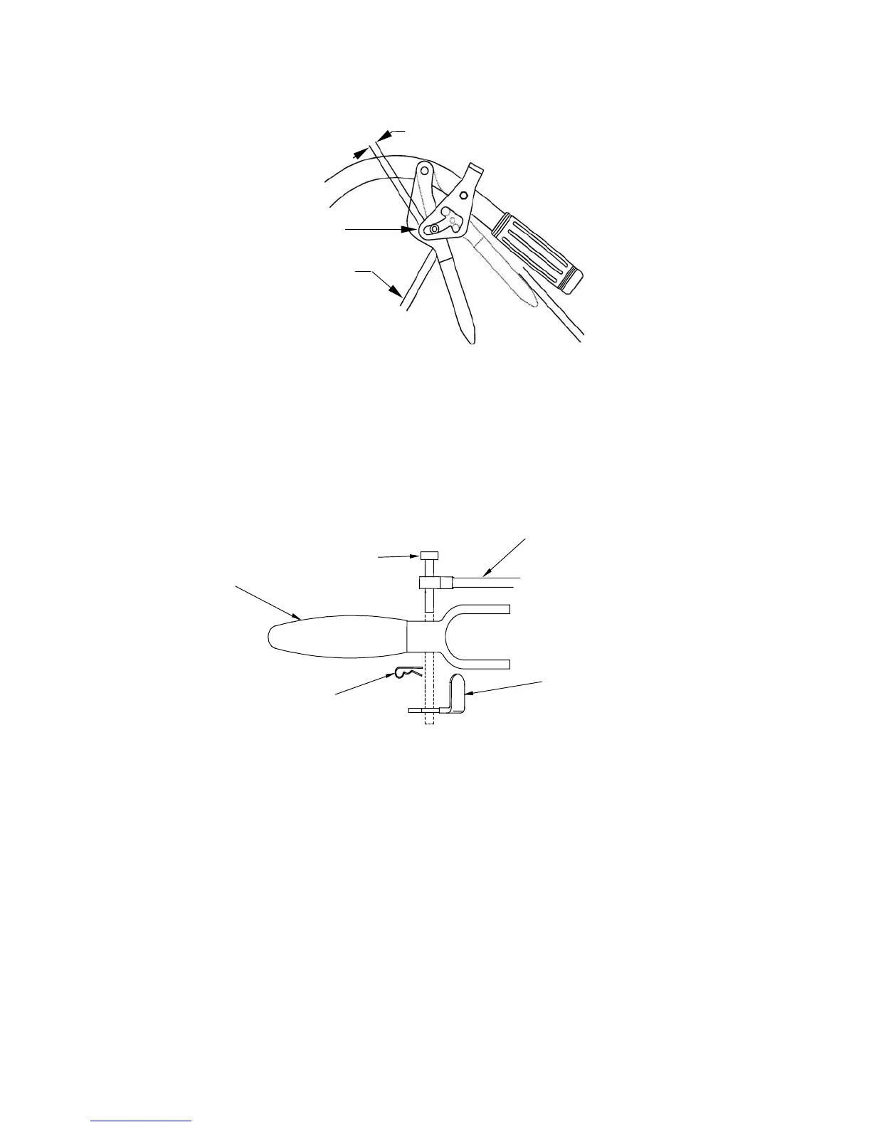
c) Adjust drive linkage length by threading into or out of the swivel until there is a
3/16" to 1/4" (.47-.64 cm) clearance between the linkage assembly and the
bottom of the slot in the neutral lock/park brake latch (See Figure 10).
FIGURE 10
STANDARD PISTOL GRIP HANDLES
NEUTRAL LOCK LEVER CLEARANCE
NOTE: Neutral lock/park brake latch clearance should be checked when
there is a slight upward force placed on the drive levers to remove any
"slack" in the linkage.
After clevis pin has been inserted, install hairpin into hole on the clevis pin
between the neutral lock/park brake latch and drive lever (See Figure 11).
Repeat procedure on opposite side of unit.
FIGURE 11
STANDARD PISTOL GRIP HANDLES
DRIVE LEVER HARDWARE LOCATION
For ECS Handles:
a) Locate the drive lever linkages which have the balljoint and jam nuts installed on
one end. Locate the (2) 5/16-18 x 1 3/4 Hex cap screws and (2) 5/16-18 nyloc
nuts in the bolt bag. Thread drive lever linkage into the swivel located on the
wheel drive idler arm. Thread in until the flat edge of the drive lever aligns with
bottom of the roller notch in the neutral lock/park brake latch when the 5/16-18 x 1
3/4 hex cap screw is inserted through the hole in the drive lever and the hole in
the balljoint. Secure with the 5/16-18 nyloc nut. Tighten nut. Repeat for the other
side. See Figures 12 and 13.
Drive Linka
e
Left Side
Shown
Neutral Lock /
Park Brake Latch
Drive
Lever
Hairpin
Clevis Pin
3/16” TO 1/4”(.47-.64 cm)
Drive Linkage
Neutral Lock /
Park Brake Latch