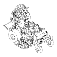
Figure7
RightHandSideofUnitShown
1.Parkbrakebracket3.Parkbrakelinkage
2.Parkbrakelever
ConnectingWireHarness
1.Routethelong,unattachedwiringharnessleadup
thelefthandsideofthehandle.
2.Connecttheconnectorontheendoftheshorter
leadtothekeyswitch.
3.ConnectthetwoagterminalstotheOPCswitch
inanyorder.
4.Continueroutingthisleaddowntherightsideofthe
handleandconnecttheconnectorontheendtothe
parkbrakeswitch.
5.Fastentheharnesstotheleftsideofhandlewithtwo
smallplasticties.Locateonetieattheupperendof
thehandlenexttotheconsoleandlocateonetieat
thelowerendofthehandleclosetothefueltank
support.
6.Repeatfortherightside.
7.Withtheremainingtwoplasticties,fastenthe
harnesstothetwosmallholesinthechannelunder
theconsole.
CheckingTirePressure
1.Checkthetirepressureinthedrivetires.Proper
inationfordrivetiresis12-14psi(83-97kPa).
2.Adjustifnecessary.
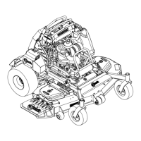
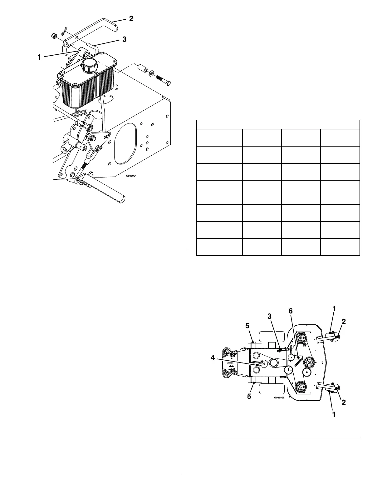
GreasingtheUnit
Note:Theunitisnotgreasedatthefactory.
LubricatettingswithNGLIgrade#2multi-purpose
gungrease.Refertothefollowingchartand
Figure8for
ttinglocationsandinitialpumps.
LubricationChart
Fitting
Locations
Initial
Pumps
Numberof
Places
Service
Interval
1.FrontCaster
WheelBearings
122
Daily
2.FrontCaster
Pivots
22
Daily
3.PTO
Engagement
Bellcrank
11
Monthly
4.PumpDrive
IdlerPivot
21
40hours
5.PumpControl
Bearings
22
40hours
6.MowerDeck
IdlerPivots
21
40hours
Number4(PumpDriveIdlerPivot)Locatedunderthe
enginedeck.
Number4and6(IdlerArmPivots)Disassembleand
greaseonceamonthundera“NoLoad”condition.
Figure8
5
 Loading...