Tech-note
tn202-2.doc - 10.01.2012
ePALM10 Product Manual
7
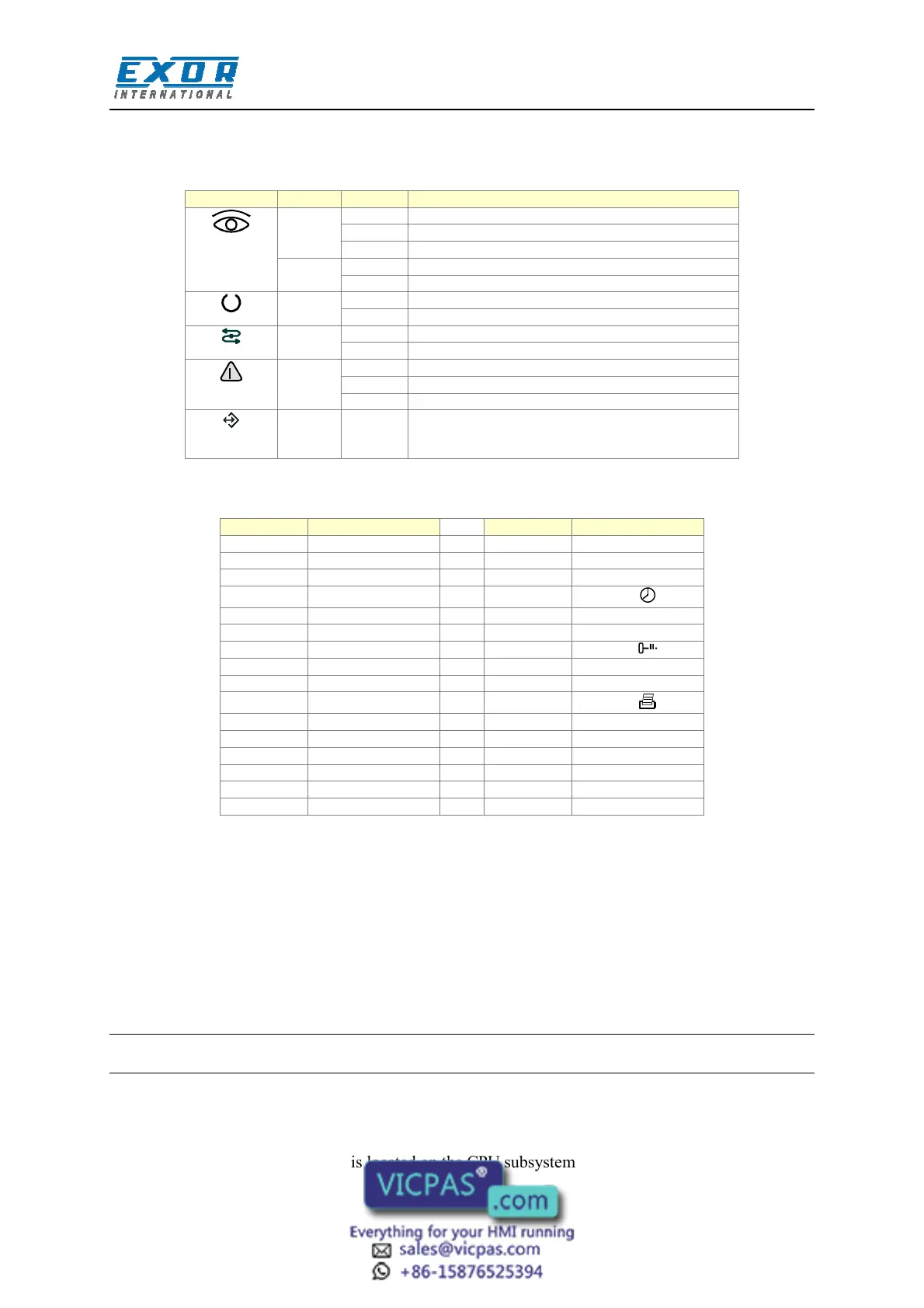
There are several dedicated LED indicators on the front panel of the unit. Functions are described in
the table below.
Red OFF No hardware problems detected
BLINK Battery low
ON Hardware fault
Green OFF No key pressed
ON While any key is pressed (visual feedback)
Green OFF Hardware fault
ON Unit in operation
Green BLINK Communication error
ON Communication OK
Red OFF No alarms
BLINK Alarm requires acknowledgment
ON Alarm active
Green May be user controlled as LED number 65 using
the Macro Editor. Turns ON when recipe/event
backup is being performed.
The RDA mapping of LED indicators is shown in the table below.
L1 F1 L17
L2 F2 L18 1
L3 F3 L19 2
L4 F4 L20
3 /
L5 F5 L21 4
L6 F6 L22 5
L7 F7 L23
6 /
L8 F8 L24 7
L9 F9 L25 8
L10 L26
9 /
L11 L27 .
L12 L28 +/-
L13 L29
L14 L30
L15 L31
L16 L32
The RDA mapping of the keypad is standard.
3.3 Battery Replacement
A Lithium battery is required for data back-up. The battery maintains the following data:
• Hardware real time clock
• Event list
• Recipe data
Note: replacing the battery will cause the loss of the data maintained by the battery.
To replace the battery follow the procedure listed below:
1) turn off the power to the device
2) using a screwdriver loose the 6 screws securing the plastic enclosure
3) open the handheld; the battery is located on the CPU subsystem
4) remove the battery