Tech-note
tn202-2.doc - 10.01.2012
ePALM10 Product Manual
6
3 Operation
3.1 Enabling Switches
Enabling switches are implemented in two different solutions in the various ePALM models:
Two independent 2-positions switches with NO contacts
One 3-positions switch with two NO contacts
The operator must operate the two independent 2-positions switches simultaneously. The two
normally open contacts are wired directly to the controller.
The 3-positions switch must be operated as described in the table.
1 Released Open Not enabled
2 Pressed Closed Enabled
3 Pressed completely Open Panic
The switch provides two normally open contacts to be wired directly to the controller.
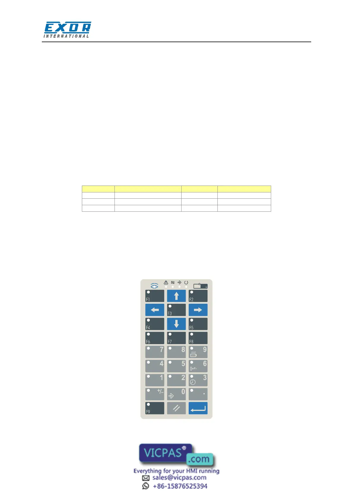
3.2 Indicators and Keypad
The standard keypad of the ePALM panels is shown in the figure below.
Custom artwork may be designed and produced on request. Please inquire for more information.
OP
OPOP
OP
091A
Figure 2 – Keypad layout