Tech-note
tn202-2.doc - 10.01.2012
ePALM10 Product Manual
14
BLUE
To Emergency Stop
Button
SHIELD TRACE
N.C.
BLACK
RED
ORANGE-PINK
P
I
N
K
YELLOW-PINK
W
H
I
T
E
GREEN-PINK
B
R
O
W
N
YELLOW
GREEN
BROWN
ORANGE
BROWN-PINK
O
R
A
N
G
BLACK
G
R
E
Y
RED
G
R
E
E
N
N
.
C
.
N
.
C
.
N
.
C
.
N
.
C
.
VIOLET-BLACK
VIOLET-RED
BLUE-BLACK
BLUE-RED
BLUE-BLACK
CYAN
N.C.
N.C.
N.C.
N.C.
N.C.
N.C.
N.C.
N.C.
N.C.
N.C.
4X1mmq
Length 25cm
CYAN-BLACK
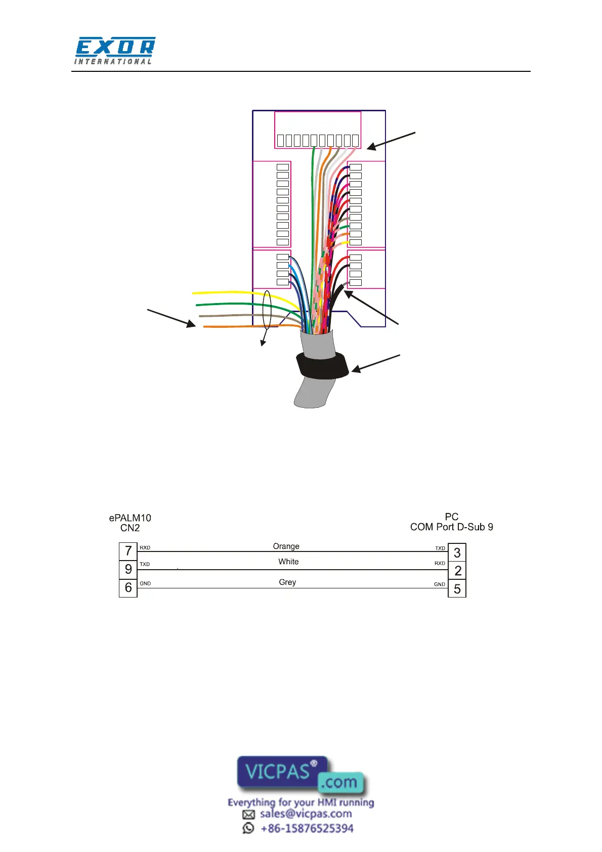
Figure 6 – Wiring layout
The figure shows the standard assembly of the communication cable.
Please note that the ferrite toroid is required for proper operation and should not be removed.
To program the ePALM10 you will need to wire at least the power supply and the programming port
connections. Connect the ePALM10 to the COM port of a PC as indicated in the figure below.
Figure 7 – Programming cable
4.1.1 Using Optional Fieldbus Modules
The ePALM versions –0061 and –0062 are compatible with some of the standard TCM
communication modules for connection to fieldbus systems.
The list of the TCM module currently supported by the ePALM product is the following:
 Loading...