GENERAL SETUP PROCEDURES
21
5.2.3
Check to be sure the correct input line voltage has been selected on the rear panel.
Either 115 volts AC or 230 volts AC. Connect the power input plug
into its socket on the rear panel of the instrument. Connect the male
end of the plug to the outlet receptacle. Please be sure that the safety
ground on the power line cord is not defeated and that you are
connecting to a grounded power source.
5.2.4
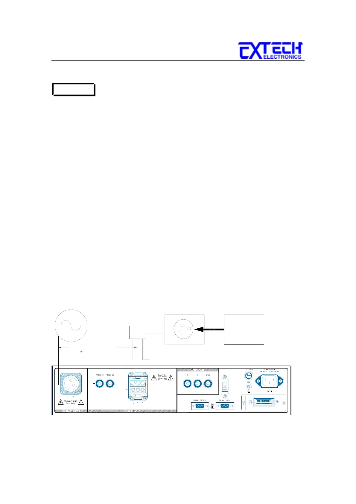
Connect the appropriate test leads to the device under test (DUT) or test fixture.
Connect the DUT power input to a AC Power Source that will provide line power
to the DUT. The Power Source must be an unbalanced single phase supply. This
means that there is only one HOT or LINE conductor and the other conductor of
the power source must be at low voltage reference potential.
Be sure that the hot
lead of the power source is connected to the L (line) terminal and the
reference or low voltage lead is connected to the N (neutral) terminal.
!!! To protect the safe of operator, please use Extech AC Power Source or Isolated
Transformer to be the power of DUT.
C
onnect the adapter box to the DUT output connector on the rear panel. Plug the
three prong line cord of the DUT into the adapter box. Be sure to connect the
safety ground to a suitable known good ground before energizing this instrument.
The DUT is now connected properly to perform the Line Leakage test that is
configured into memory. The Line Leakage Tester will measure leakage currents
in series with the ground lead of the DUT as indicated by the G-L probe
configuration on the LCD display. The
G-L configuration is known as the Earth Leakage test.
CAUTION
NEUTRAL
AC POWER
SOURCE
NEUTRAL
LINE
LINE
EARTH
GROUND
DUT
ADAPTER BOX
LINE
CORD