TEST PARAMETER SETUP PROCEDURES
26
7.4 Line Configuration
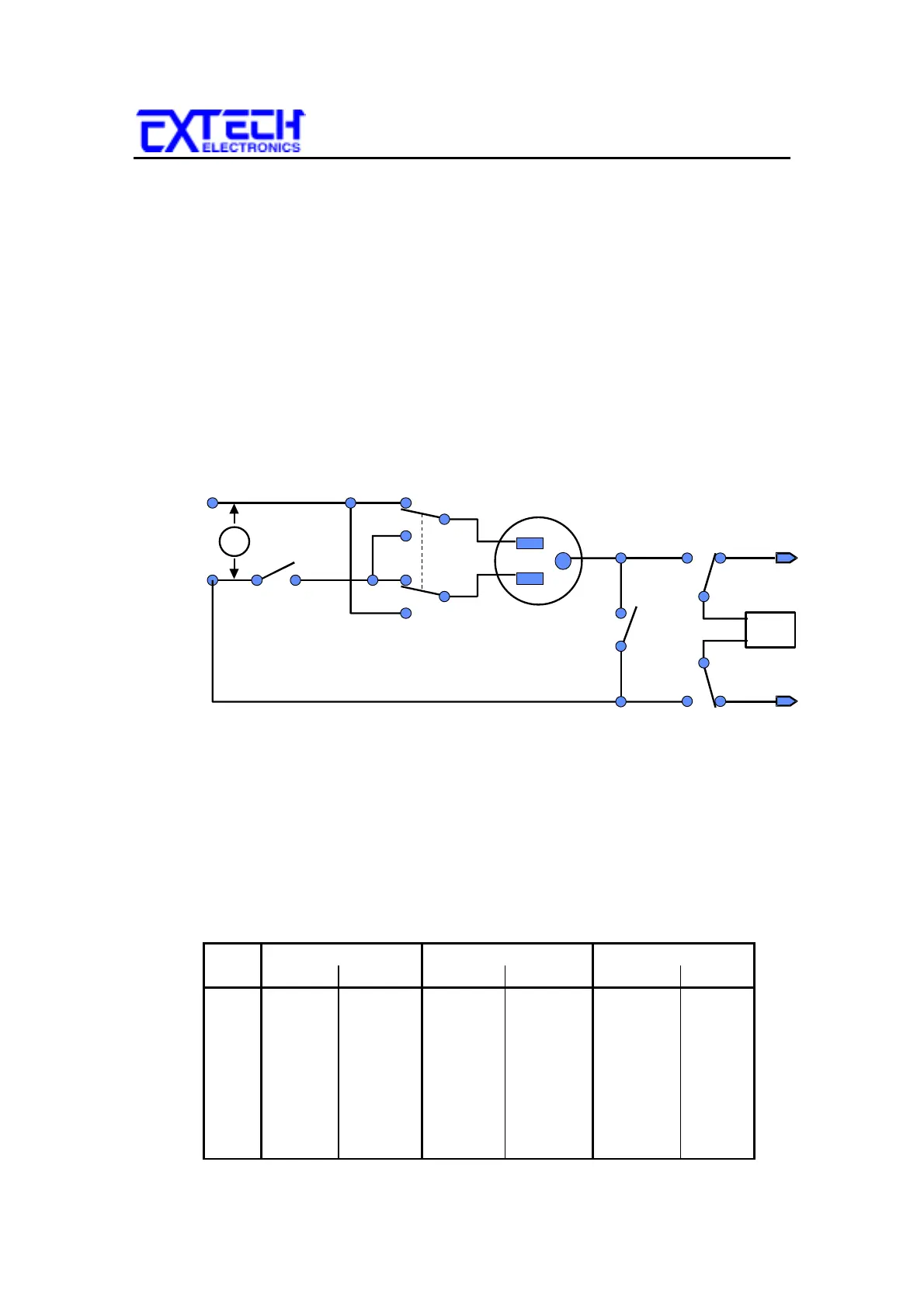
The LINE configuration is determined by the relays S1, S2 and S3 shown in figure 1
below. The three relays can be configured into eight possible combinations. The
three relays are represented on the front panel by the three LEDs (NEUTRAL,
REVERSE, and GROUND) to the left of the display. S1 relay is represented as
NEUTRAL. S2 relay is represented as REVERSE. S3 relay is represented as
GROUND. When an LED is ON it indicates that the relay is in a faulted condition
when the LED is OFF it indicates that the relay is in a normal or good operating
condition. For example, when the NEUTRAL or GROUND LED is ON it indicates
that the relay is opened and represents a fault in the line input wiring. When the
REVERSE LED is ON this represents that the relay is in position B indicating that
the Line and Neutral conductors are reversed at the DUT power outputs shown as the
DUT power receptacle in figure 1.
To change the Line configuration press the LINE key. The line configuration will
change each time the key is pressed in a sequential order represented in the table
below.
Step NEUTRAL REVERSE GROUND
Relay LED Relay LED Relay LED
1 Open ON A OFF Open ON
2 Open ON B ON Open ON
3 Open ON A OFF Closed OFF
4 Open ON B ON Closed OFF
5 Closed OFF A OFF Open ON
6 Closed OFF B ON Open ON
7 Closed OFF A OFF Closed OFF
8 Closed OFF B ON Closed OFF
B
B
S1
S3
S2
A
B
V
DUT
power
input
DUT power
receptacle
SH
Probe LO
SL
Probe HI
MD
Figure 1