RS232 & GPIB INTERFACE
44
12.5 GPIB Address
Each device on the GPIB (IEEE-488) interface must have a unique address. You
can set the address of the 7611 to any value between 0 and 30. The address is set
to 5 when the instrument is shipped from the factory. The address can only be set
from the front panel. The address is stored in non-volatile memory and does not
change when the power has been off or after a remote interface reset.
12.6 Interface Functions
The capability of a device connected to the bus is specified by its interface
functions. These functions provide the means for a device to receive, process, and
send messages over the bus. The interface functions are listed in the chart below.
All functions may be controlled over the bus except
input voltage which is
Selectable on the rear panel.
GPIB INTERFACE FUNCTIONS
Complete handshake capability
Talker/Listener functions
Service request capability
No remote/local capability
No parallel poll capability
No device clear capability
No device trigger capability
No controller capability
IEEE-488 INTERFACE
3 state driver
Test/Reset control
Setting of test status/parameters for test
LCD Display Reading
CONTROLLABLE ITEMS
Test Results Reading
DATA CODES ASCII
DELIMITER CR + LF (+ EOI)
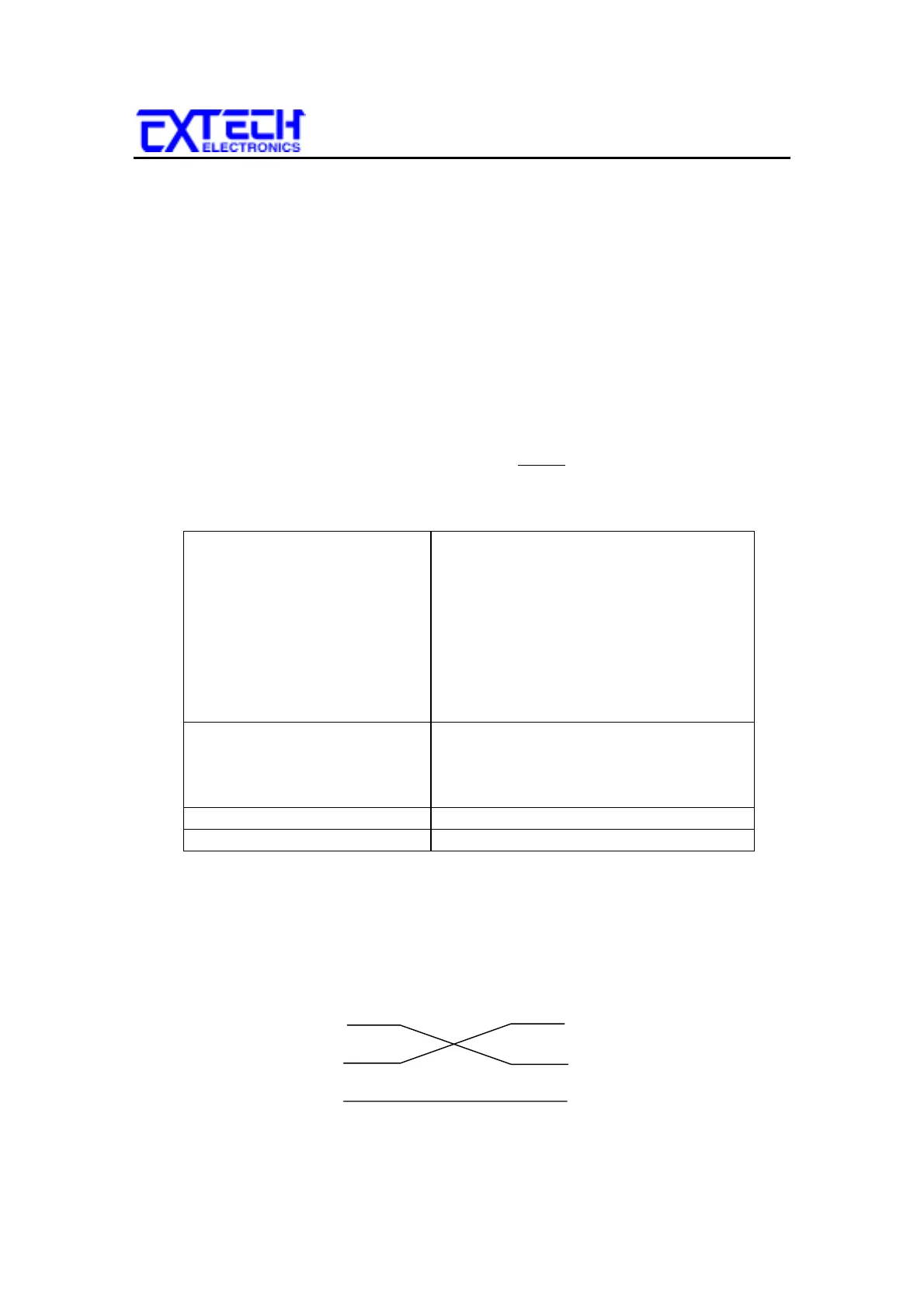
12.7 RS-232 Interface
The RS-232 cabling should be configured as follows for a 9 pin serial port
interface:
Instrument RS-232 Port PC / Bus Controller
2
3
5
2
3
5
TD
RD
TD
RD
SIG
GND
SIG
GND