382090 382091 V4.0 09/07
9
Operation
CAUTION: Turn the meter off before connecting to the equipment under test.
DANGER: Voltage input connectors U1 to U3 are common to input connector
N. Input connectors are not insulated; remove all unnecessary test leads.
DANGER: Voltage input connectors U1 to U3 are common to input connector
N. Input connectors are not insulated; remove all unnecessary test leads.
DANGER: Voltage input connectors U1 to U3 are common to input connector
N. Input connectors are not insulated; remove all unnecessary test leads.
WARNINGS
• Always set up the measurement first and then connect the test leads to the circuit.
• Make connections to the instrument first, before connecting leads to a live circuit.
• Connect the ground lead first and then the voltage leads and current probe;
disconnect in reverse order.
• Remove all test leads that are not in use.
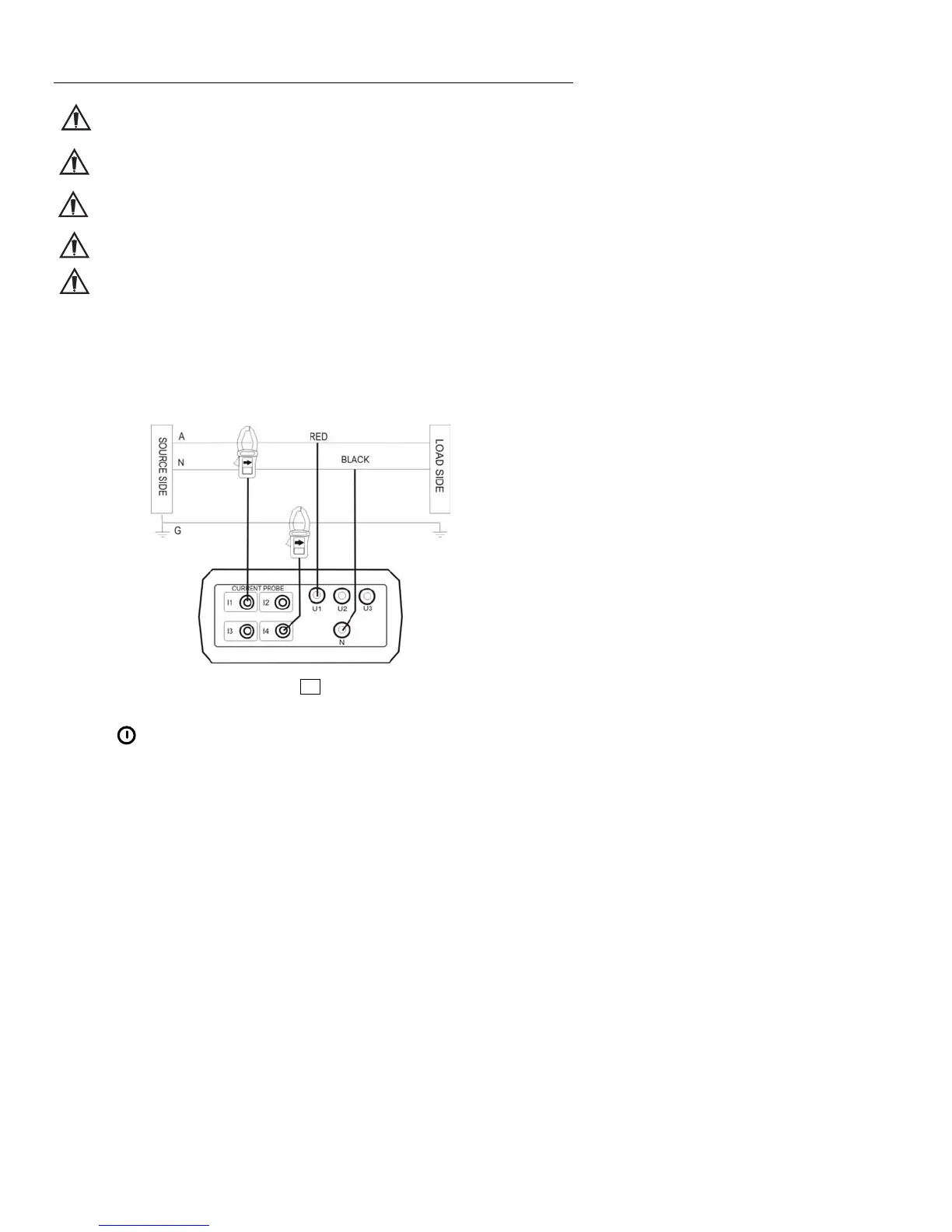
Single-Phase 2-Wire (1P2W) Power System Measurement
U1 must be connected to the voltage source during the measurement of U2, U3, I1, I2 and I3
since U1 is the main signal source for the entire meter measurement system.
A: Line, N: Neutral, G: Ground; ¨ Face the arrow toward the load.
1P2W Wiring Connection Diagram
1. Press
key to turn the meter on
2. Press the WIRING key to select 1P2W, the 1P2W annunciator will be displayed.
3. Connect the voltage test leads and current probe to the meter.
Connect the black voltage test lead to the “N” terminal.
Connect the red voltage test lead to the “U1” terminal.
Connect the I1 current probe output plug to the “I1” jack.
To measure ground leakage current, connect the I4 current probe output plug to the
“I4” jack.