382252-en-GB_V1.5 1/17
4
Operation
ZERO Adjustment of Earth Resistance Ranges
1. Connect the long test leads to the meter as follows:
a. Green lead to the 'E' terminal (Green jack)
b. Yellow lead to the 'P' terminal (Yellow jack)
c. Red lead to the 'C' terminal (Red jack)
2. Set the function selector switch to the desired measurement range. (20, 200, 2000)
3. Short the 3 test leads together by clipping them all to a single earth ground rod.
4. Press the TEST key.
5. Use the 0-Adjust knob to adjust the displayed reading to 000
6. Press to TEST key again to end the Zero adjustment process.
7. Perform this adjustment for each range.
Test Connection Diagram
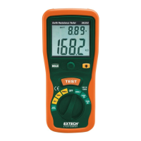
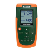
1. 382252 Meter
2. Green Test Lead (E)
3. Yellow Test Lead (P)
4. Red Test Lead (C)
5. Existing Ground rod
6. P1 Auxiliary Earth Bar
7. C1 Auxiliary Earth Bar
Earth Voltage Test
1. Set the Function selector switch to the EARTH VOLTAGE position (AC or DC)
2. Connect the 2 Voltage test leads to the meter.
Connect the black and red leads - connect the black lead to the E (green jack) and connect the
Red test lead to the C (Red jack).
3. Connect the test leads to the item under test.
4. Confirm that the voltage measurement is less than 10V AC; otherwise accurate Earth resistance
measurements cannot be made. If voltage is present (higher than 10V AC), the source of the
voltage must be found and corrected before testing can continue.
1
2
3
4
56
7