9GB
CFI EXTEL TOPTEL200- 02/2010 - V1
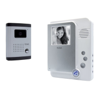
• ELECTRONIC HOUSING
One 6-core cable and 2 wires come out of the housing. The cable for connecting the plate should be passed
through a hole through the pillar (you therefore have to drill a hole through the pillar or into the wall). The other
2 wires (F) (one red and one black) should then be connected to the lock or electric door opener.
Important : the red wire’s protective sleeve (V) should only be removed at the last moment (when connecting
to the opener or lock).
Once the ideal location has been determined:
Caution: The batteries should in no event be inserted before installation has been fully completed.
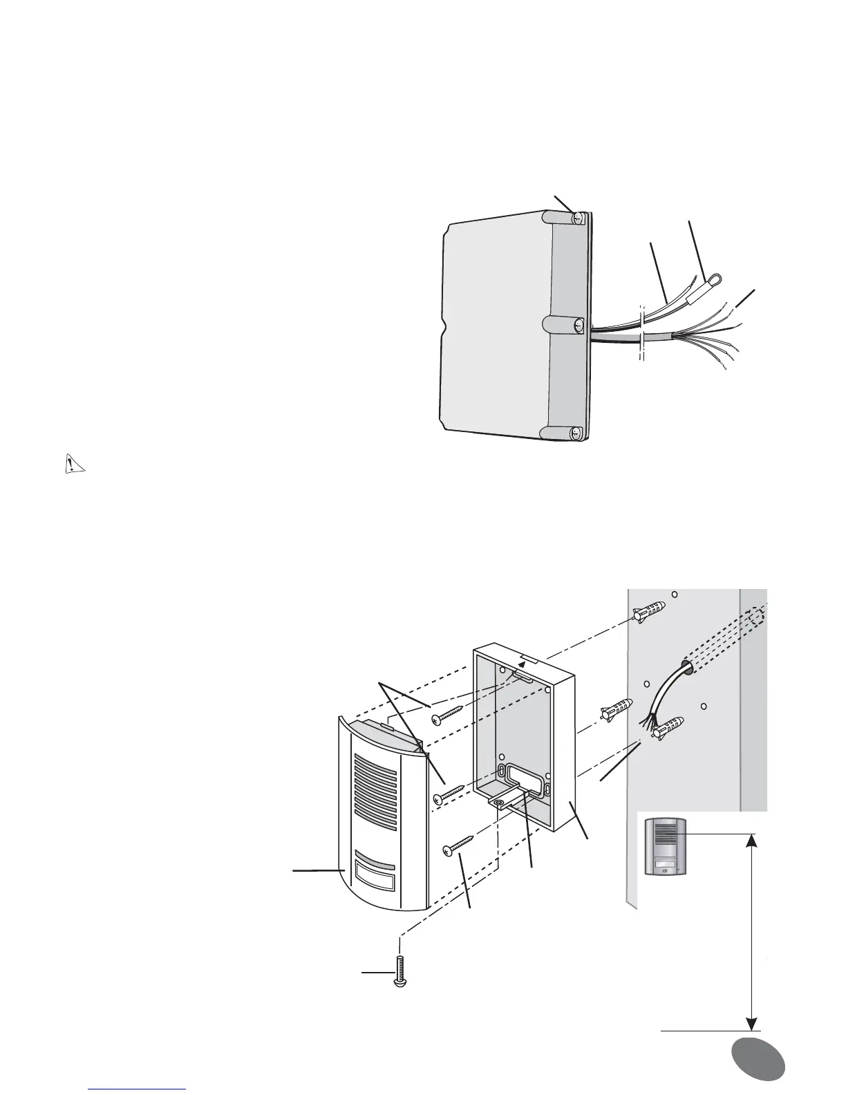
• ROADSIDE PANEL
Tip: it is recommended to pass the cables (for the roadside panel and the electric door opener) through a pro-
tective sleeve to protect them from impacts and bad weather. Do not cut the surplus of 6-core cable to prevent
problems of oxidation or poor contacts. Coil the cable up between the pillar and the electronic housing (fig. 1).
F
V
H
E
fig.2
A
C
E
D
B
F
F
fig.3
1•Remove the top cover from the housing by loosening
the 6 cross-head screws (H) (fig. 2).
Attention: do not directly touch the electronic circuit
and do not remove the red wire’s protective sleeve (V)
2•Use 2 screws to attach the housing through the 2
holes (J) located at the top and bottom (fig. 6-7)
3•Do not forget to first pass the connection cable
through the hole in the pillar to the roadside panel
1•Loosen the cross-head screw (A)
2•Move the plate (B) forwards and
remove it from the bottom
3•To prevent water leaking in from
the wall, place a silicone seal behind
the box (C) (fig. 4).
4•Using the 3 screws (F), attach the
box (C) to the wall so that the hole
(D) is in line with the cable (E).
5•Pass the connection cable
through.
6•Connect the 6 wires (E) to the
back of the plate (fig. 5).
7•Re-assemble the unit, tighten the
screw (A).
P
 Loading...