Hardware Installation
AP-8533 Access Point Installation Guide 16
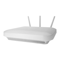
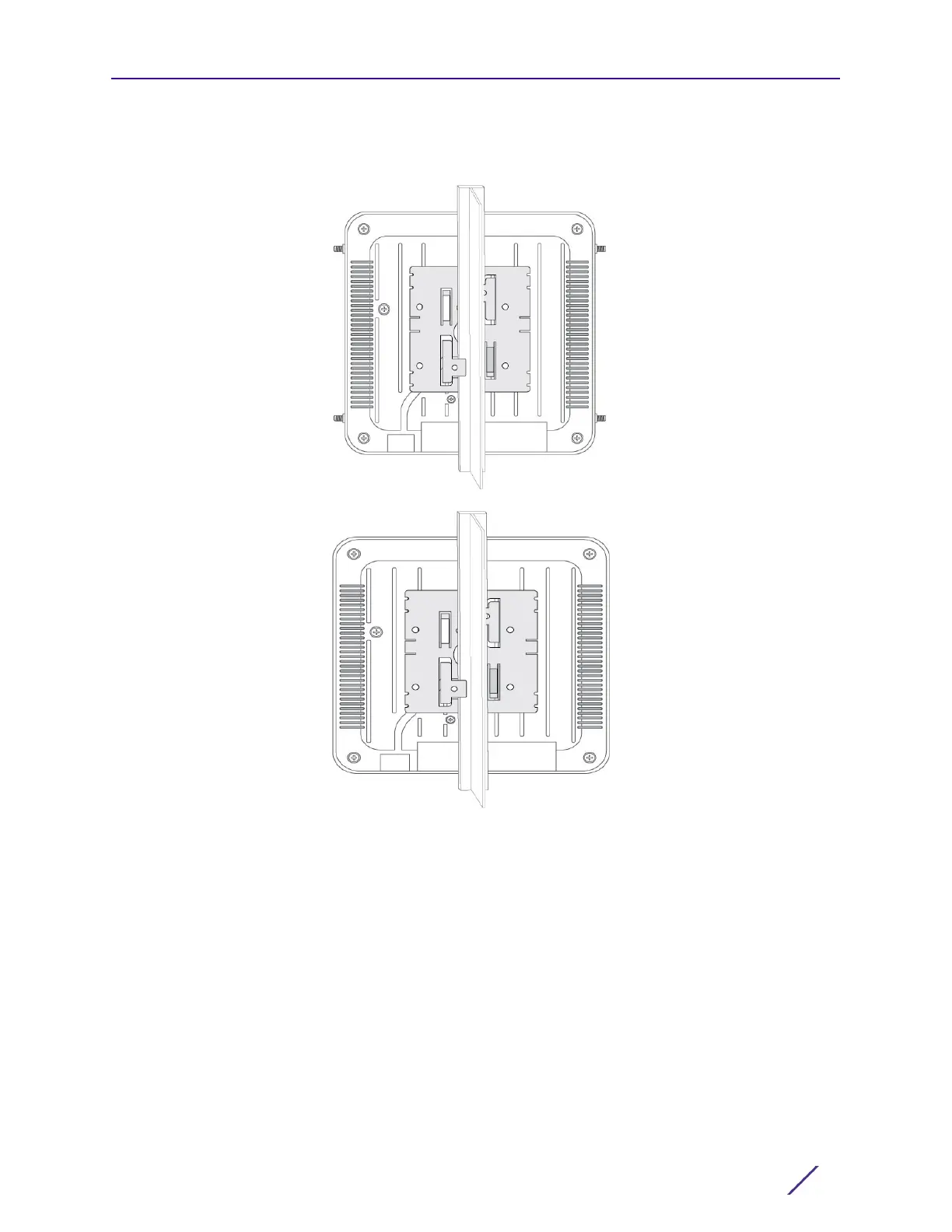
1 First install the mounting bracket on the T-bar, then attach the mounting bracket using
the mounting slots on the Access Point.
2 Cable the Access Point using either the Power Injector solution (AP-PSBIAS-2P3-ATR) or
the approved AP-8533 power supply (PWR-BGA48V45W0WW).
For Power Injector installations:
a Connect a RJ-45 CAT5e (or CAT6) Ethernet cable between the network data supply
(host) and the Power Injector Data In connector.
b Connect a RJ-45 CAT5e (or CAT6) Ethernet cable between the Power Injector Data &
Power Out connector and the Access Point’s GE1/POE port.
c Ensure the cable length from the Ethernet source (host) to the Power Injector and
Access Point does not exceed 100 meters (333 ft). The Power Injector has no On/Off
power switch. The Power Injector receives power as soon as AC power is applied.
For standard power adapter (non Power Injector) and line cord installations:

 Loading...