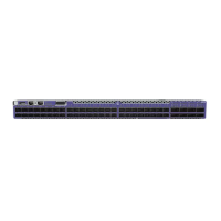
2 = USB 1 port 5 = Stacking/QSFP28 ports 7 = 1/2.5/10Gbase-T ports
3 = System LEDs
The rear panel of the switch includes:
• 1 SSD slot (unpopulated)
• Grounding lug
• 4 fan modules
• 1 Serial console port (RJ-45)
• 1 Type-A USB port for management or external USB flash
• 1 10/100/1000BASE-T out-of-band management port
• 2 power supply slots (unpopulated)
Figure 8: 5720-48MXW Rear Panel
1 = SSD slot 3 = OOB management port 5 = Grounding lug
2 = Fan modules 4 = Power supply slots 6 = Serial console port
7 = USB 2 port
ExtremeSwitching 5720 Series Overview 5720-48MXW Switch Features
ExtremeSwitching 5720 Series Hardware Installation Guide 17
 Loading...