Do you have a question about the Extreme Networks Extreme 7520 Series and is the answer not in the manual?
| Model | Extreme 7520 Series |
|---|---|
| ACL Support | Yes |
| MPLS | Yes |
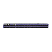
| Type | Switch |
| Power Supply | Dual, hot-swappable power supplies |
| Management | CLI, Web, SNMP |
| Layer Support | Layer 2/3 |
| VLAN Support | Yes |
| QoS Support | Yes |
| Stacking Support | Yes |
| Redundancy | Power supply, fan |
| Operating Temperature | 0°C to 40°C (32°F to 104°F) |
| Storage Temperature | -40°C to 70°C (-40°F to 158°F) |
| Jumbo Frame Support | Yes |
Guide intended for network administrators responsible for installing and setting up network equipment.
Explains typeface and command syntax conventions used throughout the document for clarity.
Resources for finding additional product information, documentation, and training courses.
Lists methods for contacting Extreme Networks for technical assistance and support.
Instructions on how to provide feedback to improve the documentation's accuracy and usability.
Details on connecting and managing the switch via console and Ethernet ports for configuration.
Information on hot-swappable fan modules and the importance of matching airflow directions.
Overview of available 800W AC/DC power supplies and their airflow characteristics for the 7520 Series.
Details on 100Gb stacking ports and their usage with Switch Engine and Fabric Engine.
Features, models, front/rear panel components, and airflow for the 7520-48Y-8C series.
Features, models, front/rear panel components, and airflow for the 7520-48XT-6C series.
Information on configuring QSFP28 and QSFP+ ports as single or partitioned ports.
Critical safety warnings and cautions for handling and installing power supply modules.
Details on 800W AC power supply options, airflow, and part numbers for Extreme 7520.
Details on 800W DC power supply options, airflow, and part numbers for Extreme 7520.
How stacked switches operate as a single unit, managed by a primary switch.
Two methods for creating stacks: native stacking and alternate stacking.
How switches are assigned slot numbers and verified during stack configuration.
Configuring redundancy to ensure stack availability if the primary switch fails.
Explains ring and daisy chain topologies for stack connections.
Definitions of key terms used in SummitStack configurations.
Commands to enable or disable the stacking-support feature on switches.
Guidelines for physical switch placement to optimize stacking.
Best practices for software configuration when deploying a new network stack.
Information on stacking different series of Extreme switches together.
Guidance on choosing and using the correct stacking cables for reliable connections.
How to use the Extreme Stacking Tool for planning and validating stack configurations.
Detailed steps for physically connecting switches using stacking cables to create a stack ring.
How to connect the stack to the management network for initial configuration.
Essential steps for planning the installation site, considering environment and requirements.
Ensuring the installation site meets necessary environmental and safety standards.
Guidance on adhering to local building and electrical codes during installation.
Recommendations for preparing the wiring closet for optimal equipment installation and access.
Maintaining appropriate temperature and ventilation for equipment performance and safety.
Guidelines for maintaining optimal humidity levels to maximize equipment lifespan.
Measures to protect the system from damage caused by electrostatic discharge.
Standards and recommendations for selecting and preparing equipment racks.
Mechanical requirements and considerations for equipment racks.
Procedures for properly grounding equipment racks to ensure safety.
Instructions on how to securely attach the equipment rack to the floor for stability.
Assessing existing cable infrastructure and meeting installation requirements.
Importance of cable labeling and maintaining accurate records for network management.
Guidelines for proper cable installation, including bend radius and strain relief.
Safety precautions and handling guidelines for fiber optic cables during installation.
Table detailing various cable media types and their maximum transmission distances.
Recommendations for using RJ45 connector jackets to prevent snagging and port damage.
Precautions to take to prevent radio frequency interference with UTP cabling.
Specific requirements for connecting PoE devices to a PoE-enabled switch.
Recommendations for planning and connecting power supplies for network equipment.
Information on selecting and purchasing appropriate power cords for Extreme Networks equipment.
Understanding UPS functions and requirements for selecting a suitable unit.
Steps to calculate equipment VA to determine the appropriate UPS size.
Importance of UPS transition time for minimizing service interruptions in stacking products.
References to relevant industry standards for cabling and grounding.
Critical safety information and warnings to review before installing any Extreme Networks switch.
List of necessary tools, equipment, and personnel for a successful switch installation.
Procedures for mounting the switch into standard 19-inch equipment racks or cabinets.
Detailed step-by-step instructions for installing the switch using a four-post rack-mounting kit.
Instructions for mounting the switch in a two-post rack, covering front and mid-mount options.
Steps for installing optional components like pluggable transceivers and cables after rack mounting.
Information on optical transceiver modules for high-speed data transmission.
Details about direct-attach copper and fiber optic cables for connecting network ports.
Information on breakout cables used for higher port densities or different speeds.
Instructions for installing 800W AC or DC power supply units into the switch.
Step-by-step guide for installing an 800W AC power supply module into the switch.
Step-by-step guide for installing an 800W DC power supply module into the switch.
List of specific tools and materials required for installing DC power supplies.
Instructions for preparing power and ground cables for a DC power supply installation.
Detailed steps for correctly connecting the ground wire to the DC power supply.
Connecting the DC power supply to the appropriate -48V source voltage.
Final steps to power up the switch after all components are installed and connected.
Guidance on connecting network interface cables to switch ports for network connectivity.
Establishing a console connection to the switch for initial setup and monitoring.
Initial login process and basic configuration for the Switch Engine operating system.
Setting the IP address and subnet mask for the management VLAN interface.
Procedure to change the switch operating system using the bootloader menu.
Method to change the switch OS through the startup menu during initial boot.
Initial login process for the Fabric Engine operating system after OS change.
Hot-swapping procedures for replacing internal power supply units without downtime.
Hot-swapping procedures for replacing fan modules to maintain cooling.
General steps for safely removing the switch from its rack mounting.
Specific instructions for detaching the switch from a four-post rack.
Specific instructions for detaching the switch from a two-post rack.
Explains the meaning of system status LEDs, including power, system, and fan status indicators.
Details on the speed and link/activity LEDs for the RJ-45 management port.
LED indicators for SFP+/SFP28 ports on the 7520-48Y-8C model.
LED indicators for 1G/10G RJ45 ports on the 7520-48XT-6C model.
Description of the green LEDs indicating link status and activity for QSFP28 ports.
LED status indications for the 800W AC power supply units, showing PSU and AC input status.
LED status indications for the 800W DC power supply units, showing PSU output and input status.
Key software capabilities like MAC addresses, VLANs, ACLs, and LAG members.
Tables listing unpackaged and packaged dimensions and weights for switches and accessories.
Sound pressure and sound power levels for different Extreme 7520 switch models.
How fan speeds adjust based on sensor readings and potential variations between fans.
Tables detailing AC and DC power consumption under various load conditions.
Data on heat dissipation and power consumption for idle and high-traffic states.
MTBF values for different 7520 series switch models at various operating temperatures.
Details on the switch's CPU, DDR4 memory, SSD storage, and buffer size.
Lists of safety, EMI/EMC, telecom, and IEEE media access standards compliance.
Operating, storage, and transportation conditions including humidity and shock resistance.
Technical specifications for the 800W AC and DC power supply units.
Electrical input and output specifications for AC power supply units.
Requirements for selecting and using AC power cords for switches and power supplies.
Pinout configuration for a standard DB-9 console connector.
Pinout details for the RJ45 console port on ExtremeSwitching devices.
Pinout mapping for an RJ45 to DB-9 adapter cable.
Key factors to consider before installing equipment, including environment and personnel qualifications.
Essential safety guidelines for handling equipment, racks, and electrical connections.
Safety recommendations for performing maintenance on Extreme Networks equipment.
Warnings and precautions related to laser radiation from fiber optic ports.
Requirements and guidelines for routing LAN system cables, including inter-building connections.
Procedures and warnings for installing power supply units and connecting power to the system.
Information on obtaining and selecting appropriate power input cords for the equipment.
Warning regarding the product's internal battery, its replacement, and disposal.
Statement of compliance with CE mark and relevant European directives for electromagnetic compatibility.
EMC warnings and compliance statements for various regions and standards.
China Compulsory Certification (CCC) statement and associated warnings.
Compliance statement for Australia's Regulatory Compliance Mark (RCM).
FCC Part 15 compliance notice, including operating conditions and warnings.
Machine noise information regulation and sound pressure level for Germany.
EMC registration statement for office use equipment in Korea.
VCCI Class A compliance statement for Japan, including potential interference warnings.
Warning about using the provided power cord only with the intended equipment.
