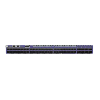
Figure 56: 5720 Series Mode and System Status LEDs
Note
Front-panel PoE ports use Amber to indicate PoE states.
Port LEDs in Default (SYS) Mode
In the default SYS mode, SPD is OFF, and the port status displays behavior for link, trac, and PoE as
described in the following table:
Table 21: Port LEDs in SYS Mode (default)
Color/State Meaning
Steady green Link is OK; port is not PoE powered
Steady amber Link is OK; port is PoE powered; no trac
Blinking green Link is OK and transmitting packets; port is not PoE powered
Blinking amber Link is OK and transmitting packets; port is PoE powered
Slow blinking amber No link, or disabled port; port is PoE powered
Alternating amber and green Port has a power fault
O Port is not PoE powered, has no link, or is disabled
Port LEDs in SPD Mode
After one press of the Mode button, the port LEDs enter the SPD Display Mode, indicated by the SPD
LED. SPD mode is used to help determine the operational speed of a port.
RJ45 and SFP ports have a single LED per port. QSFP ports have four LEDs because QSFP ports can be
divided into four dierent channels, each of which can indicate link and activity independent of the
other channels. When a QSFP port is divided, each LED indicates the rate of an individual channel.
When a QSFP port is used as single port, all of the channel LEDs indicate the rate of the single port.
Color and blink pattern indicate speeds, as referenced by the following table:
Table 22: Port LEDs in SPD Mode
Color/State Speed (RJ45, SFP) Speed (QSFP)
Steady green unused 100Gbps
Blinking green 100Mbps 50Gbps
Steady amber 1000Mbps 40Gbps
Slow blinking amber 2.5Gbps 25Gbps
Port LEDs in Default (SYS) Mode Monitor the Device
88 ExtremeSwitching 5720 Series Hardware Installation Guide
 Loading...