Table 5: AP310e power table
AP310e 802.3af 802.3at and DC
Radio 0 (sensor) 2.4G – 2×2 (19dBm)
5G – 2×2 (17dBm)
2.4G – 2×2 (19dBm)
5G – 2×2 (17dBm)
Radio 0 (2.4G) 2×2 (19dBm) 2×2 (19dBm)
Radio 0 (5G–L) 2×2 (16dBm) 2×2 (16dBm)
Radio 1 (5G–F) 2×2 (18dBm) 2×2 (18dBm)
Radio 1 (5G–H) 2×2 (16dBm) 2×2 (16dBm)
BLE On On
USB O On
PSE O On
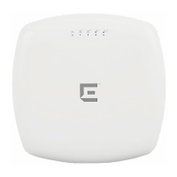
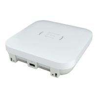
LED Indicators
The LED indicators are located on the front face of the access point but are not visibly marked.
Table 6: AP310i/e LED indicators
LED indicator LED color Description
Status Green Normal operational status
Amber Non-operational status
GE1 Ethernet Amber 100 Mbps
Green 1000 Mbps
GE2 Ethernet Amber 100 Mbps
Green 1000 Mbps
Radio 1 Green 2.4G activity
Amber 5G activity
Radio 2 Amber 5G activity
IoT (BLE) Blue Indicates BLE is enabled
Purchase Order Information
Table 7: Bracket purchase order information
Part number Description
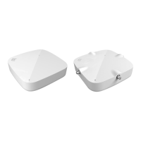
37201 Main mounting bracket for indoor access points (included in the access point
box), along with the 50 mm M3 security screw pack for main mounting bracket
30518 WS-MBI-DCMTR01 bracket
Product Overview LED Indicators
ExtremeWireless™ AP310i/e Access Points 11
 Loading...