18 Summit 200 Series Switch Installation and User Guide
Summit 200 Series Switch Overview
Summit 200-24 Switch Rear View
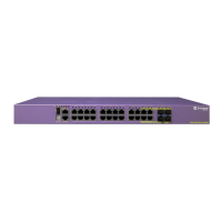
Figure 2 shows the rear view of the Summit 200-24 switch.
Figure 2: Summit 200-24 switch rear view
Table 3: Summit 200-24 switch LED behavior
Unit Status LED (MGMT LED)
Color Indicates
Green solid
Green blinking
Amber
The Summit switch is operating normally.
The Summit switch POST is in progress.
The Summit switch has failed its POST or an overheat condition
is detected.
Fan LED
Color Indicates
Green
Amber blinking
The fan is operating normally.
A failed condition is present on the fan.
Port Status LEDs (Ports 1–26)
Color Indicates
Green
Green blinking
Off
Link is present; port is enabled.
Link is present, port is enabled, and there is activity on the port.
Link is not present or the port is disabled.
Media-Selection (Fiber) LEDs (Ports 25 and 26)
Color Indicates
Green
Off
Fiber link is selected; mini-GBIC is present and being used for the
Gigabit Ethernet uplink.
1000BASE-T link is selected; the switch is using the RJ-45 port
for the Gigabit Ethernet uplink.
Unit Stacking ID Number LED
Color Indicates
N/A When several Summit 200-24 switches are interconnected
(stacked), each switch will be assigned a unique stacking ID
number that will be visible in the unit stacking ID number LED.
The switch acting as the stack master will be assigned the
number 0, which is the default.
LC24002
Power socket

 Loading...