12
IPCP Pro Series • Setup Guide (Continued)
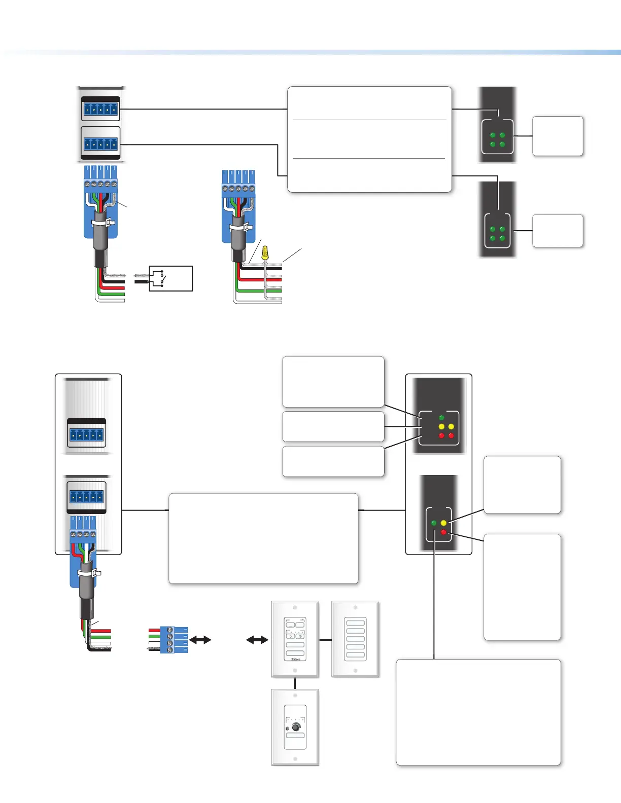
Control, Unidirectional — Flex I/O or Digital I/O
1 234G
DIGITAL I/O
FLEX I/O
3214G
FLEX
I/O
34
21
I/O
3
1
4
2
Digital I/O (digital input/output)
Congure each port as a digital input or output,
with or without +5 VDC pull-up.
Use these ports to:
• Monitor or trigger events and functions (toggle relays,
issue commands, send e-mail), once congured.
• Power LEDs or other devices that accept a
TTL signal.
Flex I/O (digital input/output or analog input)
Congure each port as an analog input or as a digital
input or output with or without +5 VDC pull-up.
Switch,
Sensor
2
3
4
G
Heat
Shrink
Over
Shield
Wires
(Switches, sensors,
LEDs, relays, or
similar items)
Rear Panel Front Panel
Digital I/O
LEDs
Light when the
corresponding
ports are active.
Flex I/O LEDs
Light when the
corresponding
ports are active.
Ground
Share the same ground among
I/O connections.
Device 4
Device 3
Device 2
Wire
Nut
Control — eBUS
eBUS
eBUS
+V +S -S G
PWR OUT = 6W
+V +S -S G
PWR OUT = 12W
MUTE
VOLUME
VIDEO
DVD
PC
DOC CAM
LAPTOP
VIDEO
PC
VOLUME
DISPLAY
OFF
ON
SLIMIT
eBUS
OVER
LIMIT
eBUS
OVER
ERROR
LINK
BUSY
Rear Panels,
Rack Mount Models
eBUS Accessory Port
Connect the rst eBUS device to this port, then connect other
eBUS devices and accessories to that device in the desired
topology (daisy chain, star, or combination).
• Wire the connectors the same at both ends for every eBUS
device.
• See the eBUS Technology Reference Guide for the
recommended distance from the control processor to the
last eBUS device and maximum quantity of devices per
control processor.
• The IPCP Pro can provide power to the button panel devices.
Front Panels,
Rack Mount Models
eBUS Link LED (green)
Lights steadily and remains lit
when the unit detects connected
eBUS devices, there are no ID
conicts, and eBUS rmware is
not currently being synchronized.
eBUS Busy LED (amber)
Blinks while eBUS rmware is
being synchronized.
eBUS Error LED (red)
Blinks if the unit detects an
eBUS ID conict.
eBUS Status LED (green)
LED is not lit — This indicates one of the following
conditions:
• No power is present.
• No eBUS devices are detected.
LED is blinking fast — An eBUS ID conict has
occurred: two devices have the same bus ID number.
LED is blinking slowly — A rmware update is in
progress: the control processor is synchronizing
rmware of the eBUS panel(s).
LED is lit steadily — Power is present with conrmed
communication and there are no eBUS ID conicts
in the entire system.
eBUS port
on an
eBUS device
(button
panel or
similar
device)
+S
+V
-S
G
+ Signal
+12 VDC
- Signal
Ground
Drain Wires
eBUS Limit LED
(amber)
Lights steadily and
remains lit while the
eBUS port uses the
maximum threshold
power.
eBUS Overload LED
(red)
Lights steadily when the
eBUS port exceeds
maximum threshold
power usage and enters
the fault state.
During this fault state,
eBUS port power is
shut down until the
power usage falls back
below the threshold.
The Over LED remains
lit during the fault state.