10
MLC Plus 50/100/200 Series • Setup Guide (Continued)
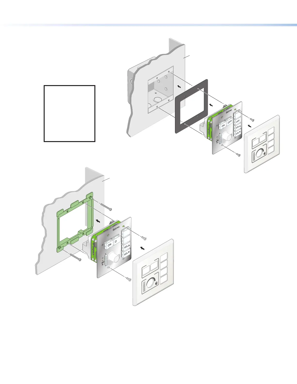
4. For non-AAP models, secure the MLCPlus to the junction box, wall or surface mounting box, or mud ring as follows (see
figures 8 and 9):
a. Insert the included screws through the oval
slots at the top and bottom of the
MLCPlus, through the plastic
spacer (if not using a
mud ring), and into
the corresponding
threaded holes in the
box or mud ring.
NOTE: If the unit is
not installed in a
mud ring, you must
install the plastic
spacer. The spacer
positions the unit to
allow the magnetic
faceplate to attach
properly and
securely.
b. Using a Phillips
screwdriver, lightly
tighten the screws
until snug.
RESET
E
E
VOL
VOL
VIDEO
PC
OFF
ON
Extron
DISPLAY
VOLUME
55
4
4
Wall
MLC Plus 100
Mud Ring
Faceplate
5. Attach the faceplate to the MLCPlus: align the faceplate openings with the buttons, knob, and LEDs and place the faceplate
against the unit (see
5
in figures 7, 8, and 9). The magnetic catches fasten the faceplate onto the front of the unit.
RESET
E
E
VOL
VOL
VIDEO
PC
OFF
ON
Extron
DISPLAY
VOLUME
55
4
4
Wall
Junction
Box
Faceplate
MLC Plus 100
Plastic Spacer
Figure 8. Installing the MLCPlus
in a Junction Box
Figure 9. Installing the
MLCPlus in a Mud Ring