9
• Place the AAP opening of the MLCPlus faceplate over the cluster of AAPs to check for correct fit. Make sure that the
edges of the AAPs all fit within the faceplate AAP opening so that no edges or corners catch or prevent the faceplate
from laying flat against the AAP mounting bracket. If needed, loosen the nuts, adjust the position of one or more AAPs,
and retighten the nuts.
2. For all models, follow instructions in “Mounting”, below.
Mounting
NOTE: Extron recommends taking safety precautions to avoid electrostatic discharge issues during installation.
Prior to mounting:
1. If it has not already been done, feed all device cables through the wall or furniture and, if applicable, through the plastic spacer.
NOTE: If the unit is not installed in a mud ring, you must install the plastic spacer. The spacer positions the unit to allow
the magnetic faceplate to attach properly and securely.
2. Ensure that cables are connected to the MLCPlus rear panel and to any AAP devices or plates.
3. Disconnect power at the source from all devices in the system.
Mount the MLCPlus as follows:
1. For AAP models, first attach AAP devices or blank AAP plates to the metal AAP bracket (see Step 8: Complete the
Physical Installation on page8.
2. For all models, insert the cabled MLCPlus into the mud ring or junction box within the wall or furniture, aligning the mounting
holes in the MLCPlus with those in box or mud ring.
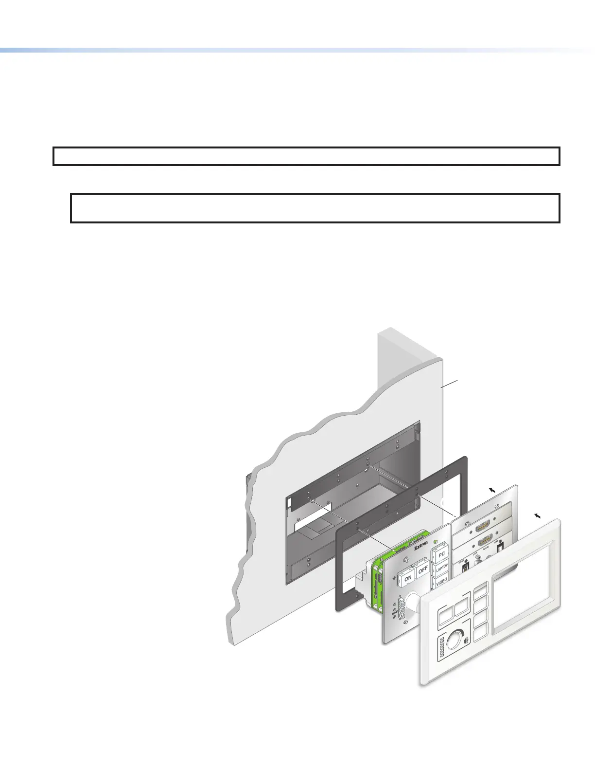
3. For AAP models, fasten the MLC to the junction box, wall box or
surface mounting box, or mud ring as follows (see figure 7):
a. Insert screws through the mounting holes in the unit
or AAP bracket, then into the mud ring, or insert them
through the plastic spacer and into the wall box, and
loosely tighten the screws.
b. Align the faceplate with the MLCPlus and place
it against the front of the unit, allowing
the magnetic catches to fasten the
faceplate onto the unit. Check the
alignment and fit. The faceplate
must sit flush against the
front of the MLCPlus and
against the AAP bracket
without catching on any
LEDs, buttons, or AAP
edges, or on the edges of
the MLCPlus metal plate.
If the faceplate seats in
place correctly, remove
the faceplate, tighten the
screws, and reattach the
faceplate. The installation is
complete. If not, proceed
to step3c.
c. If necessary, remove the
faceplate, loosen the
mounting screws, and
adjust the position of the
MLCPlus, AAP mounting
bracket, or individual AAP
devices. Place the faceplate
over the unit to check the
fit, remove the faceplate, and
tighten the mounting screws once
all the elements are positioned to
allow correct alignment with the
faceplate.
RESET
E
OFF
ON
PC
VIDEO
MUTE
LAPTOP
HDMI
VGA
AUDIO
USB
Extron
DISPLAY
VOLUME
Wall
MLC Plus 100 AAP
Faceplate
Plastic Spacer
Wall
Box
55
3
3
Figure 7. Assembling the Spacer, Unit, AAP Bracket, and Faceplate for
an AAP Model