F.W. BELL 8000 Series Gauss/Tesla Meter Instruction Manual
Appendix A – Understanding Flux Density A-2
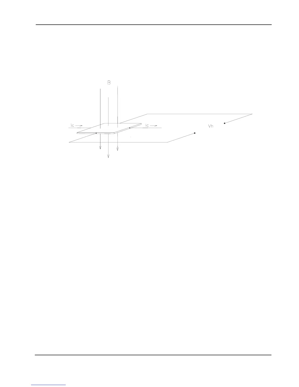
Measurement of Flux Density
A device commonly used to measure flux density is the
Hall Effect sensor. A Hall Effect sensor
is a thin slice of a semiconductor material to which four leads are attached at the midpoint of
each edge, as shown in Figure A-2.
Hall Effect
Sensor
Figure A-2 Hall Effect Sensor
A constant current (I
C
) is forced through the material. In a zero magnetic field there is no
voltage difference between the other two edges. When flux lines pass through the material the
path of the current bends closer to one edge, creating a voltage difference known as the Hall
voltage (V
H
). In an ideal Hall generator there is a linear relationship between the number of flux
lines passing through the material (flux density) and the Hall voltage.
The Hall voltage is also a function of the
direction in which the flux lines pass through the
material, producing a positive voltage in one direction and a negative voltage in the other. If the
same number of flux lines passes through the material in either direction, the net result is zero
volts. This sensitivity to flux direction makes it possible to measure both static (DC) and
alternating (AC) magnetic fields.
The Hall voltage is also a function of the
angle at which the flux lines pass through the material.
The greatest Hall voltage occurs when the flux lines pass perpendicularly through the material.
Otherwise the output is related to the cosine of the difference between 90
° and the actual angle.
The sensitive area of the Hall Effect sensor is generally defined as the largest circular area
within the actual slice of the material. This
active area can range in size from 0.2 mm (0.008”)
to 19 mm (0.75”) in diameter. Often the Hall Effect sensor assembly is too fragile to use by itself
so it is often mounted in a protective tube and terminated with a flexible cable and a connector.
This assembly is known as a
Hall probe. For more information on Hall Probes see Section 3 –
Probes.
 Loading...