21
ENGLISHENGLISH
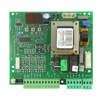
6) Slide the travel stop plate on the rack in the opening
direction. When the LED of the opening travel limit switch
(FCA) in the 746 electronic control unit (Fig. 23) goes out,
advance the travel stop plate by approximately 45 mm,
and fix it to the rack by tightening the screws.
7) Move the gate by hand towards its closed position, stop-
ping approximately 2 cm from the physical travel stop.
8) Slide the travel stop plate on the rack in the closing direc-
tion. When the LED of the closing travel end limit switch
(FCC) in the 746 electronic control unit goes out (Fig. 23),
advance the travel stop plate by approximately 45 mm,
and fix it to the rack by tightening the screws.
9) Re-lock the system (see paragraph 8).
10) Run a complete cycle of the gate, to check whether the
limit switch trips correctly. To adjust the limit switch posi-
tions, operate brake trimmer TR1: when the trimmer is
rotated clockwise, the braking space is decreased; when
the trimmer is rotated counterclockwise, the braking space
is increased.
Notes on positioning the travel stop plates
• The distance between the limit switch and the travel stop
plate must be < 5mm (Fig.11).
• When nylon rack is used, the limit switch plate will be
mounted without the support. Fix the plate directly on the
rack with the self-tapering screws. Adjust the limit as men-
tioned above.
• To avoid damaging the operator and/or interruptions to
service, leave a distance of at least 2 cm from physical
travel stops of the gate.
5.6. TORQUE ADJUSTMENT
The 746 automation system is equipped with an anti-crushing
system comprising an electronic sensor and a mechanical
clutch which (according to the selected operation) either
stops or reverses gate motion when the gate encounters an
obstacle.
When the obstacle is removed, a new command impulse must
be given before the gate resumes the opening or closing
movement. The torque limiting clutch must be set in compliance
with current standards.
To adjust the threshold of the anti-crushing system, proceed as
follows:
1) Switch off the power supply.
2) Hold the driving shaft in position by means of the lever
supplied, and adjust the clutch adjusting screw, as shown
in Fig. 33.
To increase torque, turn the screw clockwise.
To decrease torque, turn the screw counterclockwise.
Ü The operator is supplied with the clutch set to maximum
torque. It will therefore be necessary to turn the adjuster
screw counterclockwise to obtain the optimum adjust-
ment.
3) Switch on the power supply and check whether the anti-
crushing system operates correctly.
Ü When tripped, the anti-crushing system either stops the
opening movement or reverses the closing movement.
6. TESTING THE AUTOMATION
When installation is complete, press fit the covers over the
operator fixing bars and fix the top cover using the screws and
bushes supplied (Fig. 34).
Fig. 33
Fig. 35
Fig. 32