Do you have a question about the FAAC 770 and is the answer not in the manual?
General safety precautions and warnings to prevent severe injury or death when operating the gate.
Guidelines for safely installing the gate operator and ensuring proper gate function and safety.
Guidelines for constructing and installing vehicular gates to ensure safety and compliance with standards.
Emphasizes qualified personnel, main power switch, and avoiding compensation for damaged gates.
Proper use of the equipment, manufacturer liability, and basic safety practices during operation.
Defines Class I operators for single-family dwellings.
Defines Class II operators for commercial and public access locations.
Defines Class III operators for industrial and limited access locations.
Defines Class IV operators for guarded and restricted access locations.
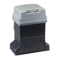
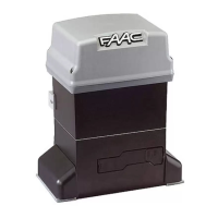
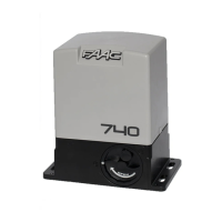
Detailed technical data including power, current, torque, temperature, and dimensions.
Wiring diagram and guidelines for connecting electrical components and power.
Visual representation of the operator's physical dimensions.
Requirements for the gate structure and its components before operator installation.
Steps for digging, placing, and securing the foundation box for the operator.
Assembling release levers, fitting the support bracket, and preparing the guide bracket.
Steps for mounting the operator, connecting levers, and fastening the cover box.
Steps to return the gate operator to its normal powered state after manual operation.
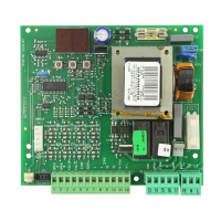
Detailed electrical specifications of the control board, including power, inputs, and outputs.
Identification and description of the control board's main components and connectors.
Instructions for connecting radio receivers to the control board.
Requirements for entrapment protection devices, including photocells and edge sensors.
Explanation of how opening safety devices protect against entrapment during gate opening.
Explanation of how closing safety devices protect against entrapment during gate closing.
Details on UL325 requirements for monitoring safety devices using FAILSAFE function.
Configuration of operating logic modes using DIP switch settings for various gate behaviors.
Procedure for automatic learning of gate movement times and slowdown points.
Procedure for manual learning of gate movement times and setting slowdown points.
Guidelines for safely connecting AC power to the gate operator system.
Details about the high-efficiency switching power supply and its fuse.
Describes the operational logic and behavior for Logic 'E' system status.
Describes the operational logic and behavior for Logic 'A' system status.
Describes the operational logic and behavior for Logic 'S' system status.
Describes the operational logic and behavior for Logic 'EP' system status.
Describes the operational logic and behavior for Logic 'AP' system status.
Describes the operational logic and behavior for Logic 'SP' system status.
Describes the operational logic and behavior for Logic 'B' system status.
Describes the operational logic and behavior for Logic 'C' system status.
Details on connecting a shadow loop detector for enhanced gate safety.
| Max Gate Weight | 500 kg |
|---|---|
| Max Gate Length | 5 m |
| Absorbed Power | 300 W |
| Thermal Protection | 140°C |
| Operating Temperature | -20°C to +55°C |
| Protection Class | IP44 |
| Motor Voltage | 230V AC |
| Type | Swing gate operator |
| Power Supply | 230 Vac (50-60Hz) |