7
FAAC MODEL 950 BM Door Operator
1.2 DOOR MAX OPENING ANGLE
According to the type of mounting and following the installation dimen-
sions shown in Tables A or B, different door max. opening angles can
be obtained according to the lintel thickness. Table 5 and 6 shows
the maximum values of the opening angles that can be obtained in
thedifferentcongurations.
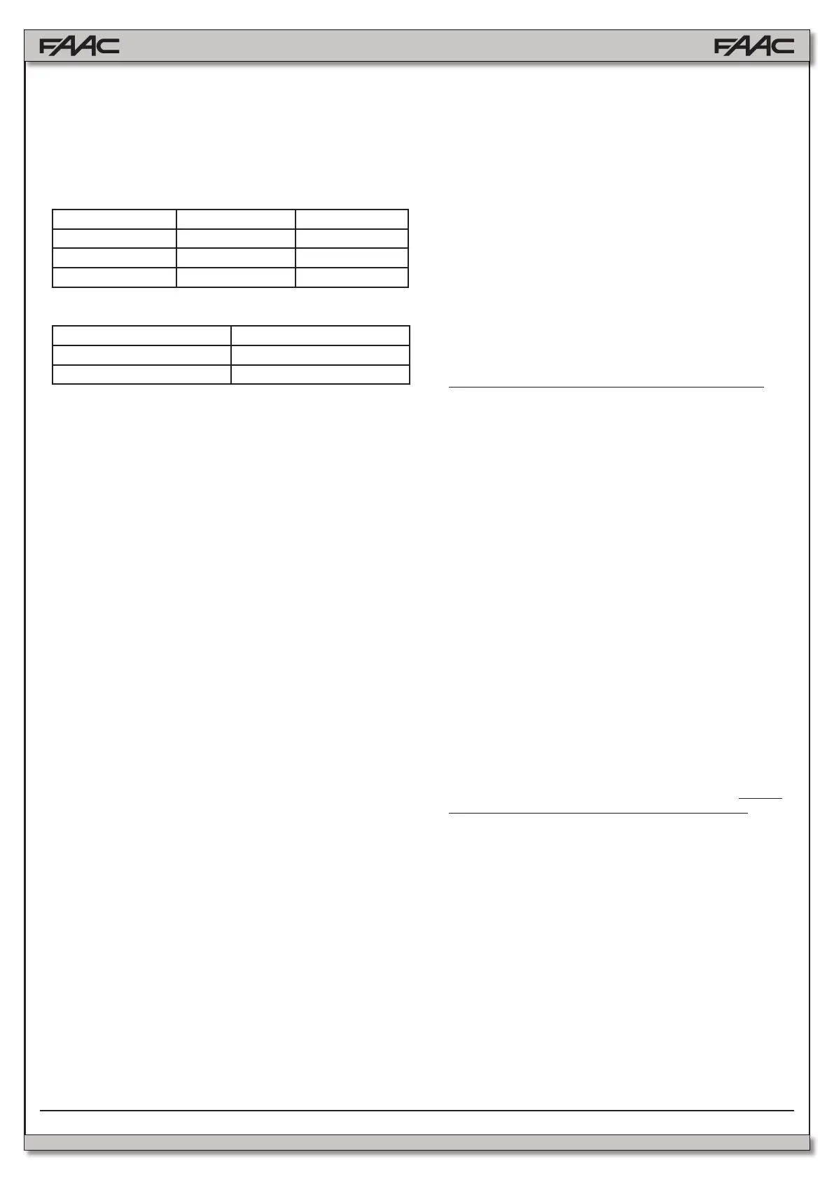
Tab.5: Door max opening angle with pushing articulated arm
Type of installation Jamb depth (mm) Max opening angle
operator on lintel 0 100°
operator on lintel 125 110°
operator on lintel 250 125°
Tab.6: Door max opening angle with sliding arm
Jamb depth (mm) Max opening angle
0 90°
160 105°
1 950 BM operator
2 Microwave radar / Passive infrared sensor
3 T20E outdoor key-operated selector switch
(KEY command)
4 Emergency Closing/Opening pushbutton
5 KP-CONTROLLER programming unit (optional)
6 KP-CONTROLLER inhibition switch (optional)
7 24 Vdc electric lock
8 Junction box
Notes: 1)Tolayelectriccables,usesuitablerigidand/orexiblepiping.
2) Always keep the low voltage accessory connection cables
separate from the 115 V power cables. To avoid interference,
use separate sheaths.
3. INSTALLATION
3.1. PRELIMINARY CHECKS
To ensure correct operation of the automated system the structure of
the existing door must meet the following requirements:
- lengthandweightasspeciedinTable3(paragraph1.1.);
- max.jambdepthasspeciedinTable4;
- robustandrigidstructureoftheleaf;
- goodconditionoftheexistinghinges;
- smooth, uniform movement of the leaf with no abnormal friction
duringitsentiretravel;
- “neutral” position of the door during its entire travel. If the door tends
to close or open, check the alignment of the hinges.
- Presence of mechanical travel stops.
3.2. MOUNTING THE OPERATOR
1) For details on the mounting position of the operator and the type
of arm to use (pushing or sliding), refer to the relevant mounting
table and drill the holes required to mount the operator and the
arm.
NOTE:Thetwointermediateoperatorxingholesarenotinacentral
position (see Mounting tables). The holes are offset in order to ensure
that the operator is mounted with the correct direction of rotation of
the mechanism.
The mounting tables are the following:
Table A: LINTEL MOUNTING (PUSHING ARTICULATED ARM):
Outward opening.
Table B: LINTEL MOUNTING (SLIDING ARM):
Inward opening.
2) Mountthecasingxingbracketsasshowning.3accordingto
thetypeofmountingtobemade.Tightenthescrews(g.3-ref.1)
andtthescrews(g.3-ref2)withouttighteningthemcompletely.
3) Mount the operator using the six M6 screws and washers provided.
Warning:
- The structure of the lintel (or the door) at the operator mounting
positionmustnotexhibitanysignicantdeformation.
- Theoperatormustbemountedparalleltotheoor.
NOTE: If the sliding arm is to be used, the driving arm must be mounted
beforetheoperatorisxedonthelintel(seeparagraph3.3.2.).
3.3. MOUNTING THE DRIVING ARMS
3.3.1. MOUNTING THE PUSHING ARTICULATED ARM
(g.5)
1) Close the door.
2) Freearms(1)and(2)bylooseningthexingdowel(3)asshown
ing.5.
3) Fit arm (1) on the coupling of the operator transmission shaft by
meansofthestandardshaft(8)andthescrew(4)provided(g.5).
The arm must be mounted perpendicular to the closed door.
Note: If a greater distance between the operator and the arm is requi-
red, use the shaft modular extensions, available as accessories, until
the required distance is reached. (see Table A/B).
4) Mount plate (5) of arm (2) on the door or the lintel using the two
M6 screwsandthe washers provided (g. 5). The installation
dimensions are given in Table A/B.
5) Slacken the xing screw (6) and assemble the two arms by
tighteningthedowel(3)(g.5).
6) Turn arm (1) until arm (2) is perpendicular to the closed door or
thelintelasshowning.5(a-b),slidingthespacer(7)alongarm
(2).
7) Tightenthexingscrew(6)betweenthetwoarms.
The length of arm (2) is given in the relevant mounting tables. If
necessary, cut off the section of the arm extending beyond the
articulationandthencoveritsendusingthecapprovided(g.5).
8) Check manually that the door is free to open and close fully and
that it comes to rest against the mechanical stops. If the door
does not close correctly, adjust the return spring as described in
paragraph 9.
Important: The two driving arms must never touch.
NOTE: it is advisable to always adjust the operator internal mechanical
stops(g.1-ref4),open/closed,sothattheyarereachedatthesame
time when the leaf mechanical stops are reached.
3.3.2. MOUNTING THE SLIDING ARM
(g.6)
1) Mount arm (1) on the operator transmission shaft by means of
thestandardshaft(5)andthescrew(2)provided(g.6).The arm
mustbettedpointing45°outwardsasshowning.6(a).
Note: If a larger distance is required between the operator and the
arm use the shaft modular extensions available as accessories, until
the required distance is reached (see Table C/D).
Warning:Mountarm(1)onthetransmissionshaftbeforettingthe
operatoronthelintel(g.6).
2) Inserttheteonslide(3)insidetheslidingguide(4)(g.6).
3) Pullarm(1)inwardsmanuallyasshowning.6(b)andsecure
the sliding guide (4) by means of two M6 screws on the closed
door as shown in Table C/D.
4) Check manually that the door is free to open and close fully and
comes to rest against the mechanical travel stops. If the door
does not close correctly, adjust the return spring as described in
paragraph 9.
2. ELECTRICAL SETUP (g. 2a Standard system)
 Loading...


