24
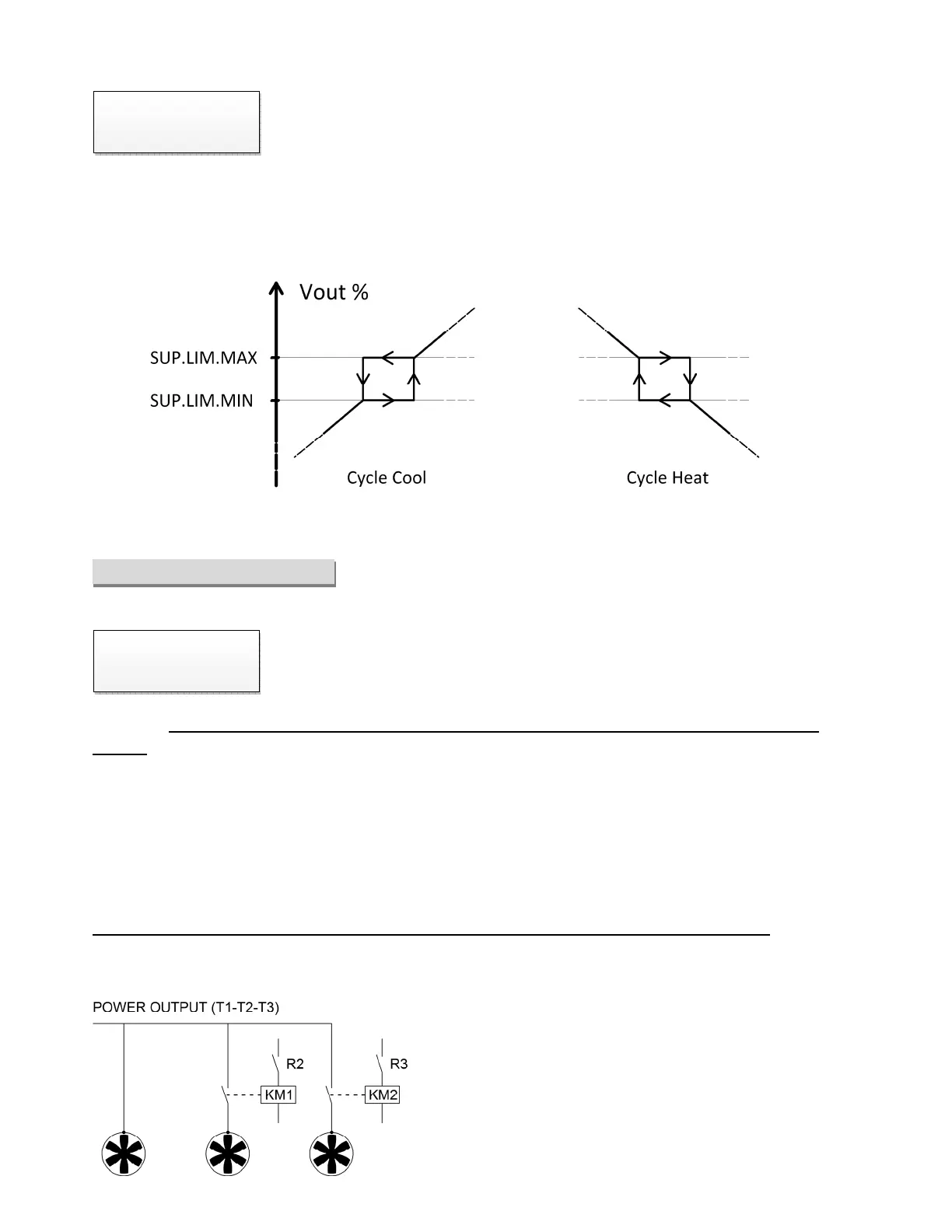
Higher voltage of the jump window.
Min. Sup.Min.Lim.1 Max. Sup.Min.Lim.2 Def. 30%
(this parameter is visualized only if “Suppress.1” is ON).
The functions “Suppress.2” and “Suppress.3” with corresponding limits operate alike the “Suppress 1” and are
prioritary functions on any operating cycle.
RELAY SETTINGS
Enables the internal relay based on the following settings:
Default (Def.) : enabled relay in a condition of regular operating, disabled relay in
emergency case (see image page 9)
Hysteresis: This function, for “Chiller mode” and “Dry cooler mode”, is used for the control of solenoid valves/
sprayers. Relay enabled above the Lim.max.relay value and disabled under the Lim.min.relay value. The Lim.max
parameters. and lim.min. are expressed in ° C or bar depending on the setting. They are displayed only when "relay"
is set to "hysteresis."
[WITH CARD S1] The relay exchange in relation to the priority probe.
WARNING : This function, if used with ambient temperature sensor, expects a temperature threshold (Default 10°C)
below which the relay will not be excited. See section “Advanced Settings – T° Limit” for modify the value.
Load Partialization [WITH CARD S1 and AMBIENT PROBE CONNECTED]:
This feature, for “Chiller mode” and “Dry cooler mode”, allows you to split the load in 2 or 3 subgroups connected
to the power out through two contactors KM1 and KM2 (Class AC-2) respectively controlled by relay R2 and R3 of S1
card.