26
(If the function is activated and the temperature probe is connected the dispaly
shows “Δ”.) Def. ON
Percentage Variation Band (G%)
Min. 20% Max. 65% Def. 25%
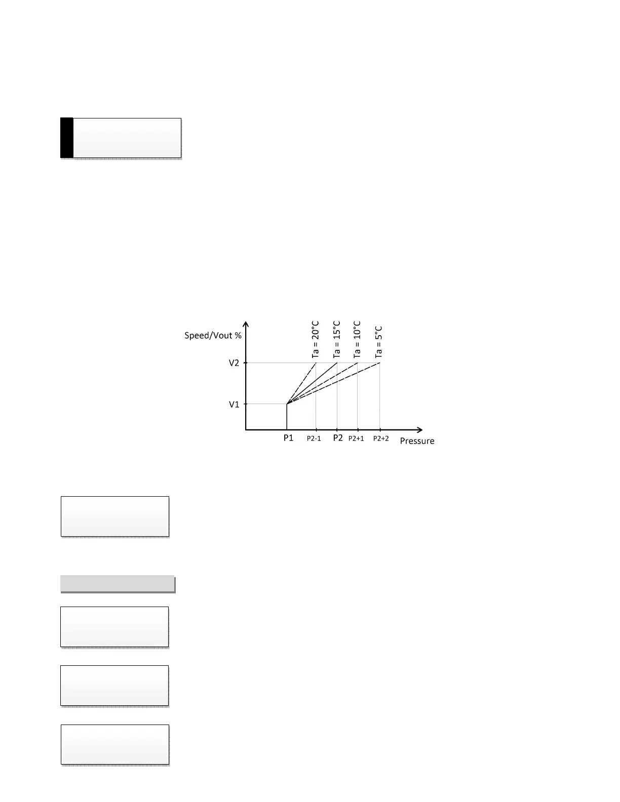
With the parameter (G%), it is possible to establish the variation of the proportional band every 5°C of deviation
from the reference ambient temperature of 15°C. The variation will be an increase for lower temperatures and
decreases for higher temperatures (with a minimum limit set at 2 bar).
Ex. With reference to the "Parameters Cycle Cooling [CO1]" of page 12 (proportional band = P2-P1 = 4), and with G =
25%, imagining to work at an ambient temperature of 10 ° C, the band increases of 4x0,25 = 1bar, then at ambient
temperature of 10°C, the control will command the load at maximum speed with a pressure of P2+1bar. If the
ambient temperature drops to 5°C, the bandwidth increases by 4x0,25x2 = 2bar, then at ambient temperature of
5°C, the control will command the load at maximum speed with a pressure of P2+2bar.
Threshold for Hysteresis [WITH S1 CARD and at least one RELAY set to “Hysteresis”]
Defines the external temperature threshold below which the relay will not be excited.
This avoids the formation of ice using sprayers at low outside temperatures.
Min. 5 °C Max. 25 °C Def. 10 °C
DIAGNOSIS
Days and hours of operation of the adjuster
Caution: in case of reset this value won’t be reset.
Internal temperature of the adjuster represented in centigrades.
Quantity of stops due to the missing of a power supply phase or high disturbances in the
power supply line.
CHILLER