SECTION 1 – INSTALLATION
Important: Check that no damage has occurred to the appliance or power cable during
transit.
If damage has occurred do not install/use the appliance.
Installation, periodic testing, repair and fixed wiring connections should only be
undertaken by a competent electrician.
Ensure that the mains power cable is routed free from the appliance to avoid damage.
We recommend supplementary electrical protection with the use of a residual current
device.
Take care when removing or replacing cast iron components as they are heavy items.
Pan Support - 5kg
UNLESS OTHERWISE STATED, PARTS WHICH HAVE BEEN PROTECTED BY THE MANUFACTURER
ARE NOT TO BE ADJUSTED BY THE INSTALLER.
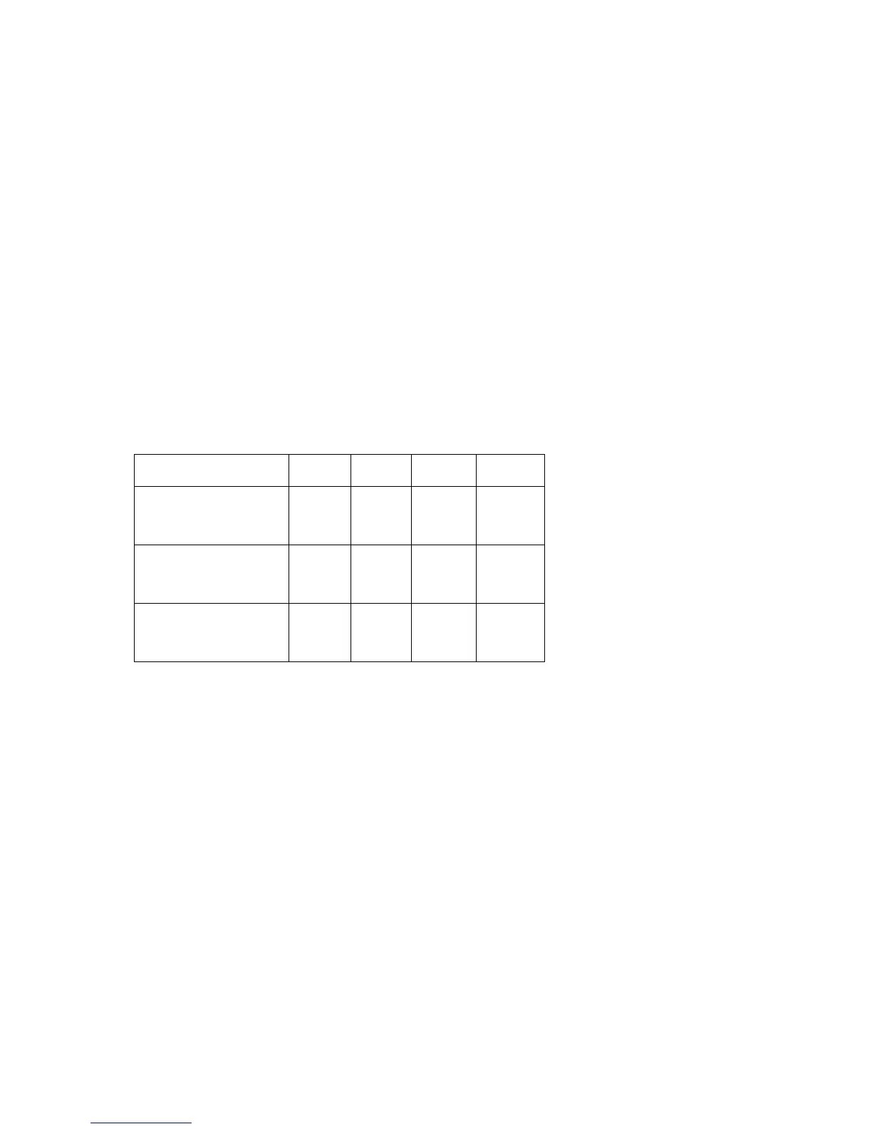
1.1 MODEL NUMBERS, NETT WEIGHTS and DIMENSIONS
1.2 SITING
All units, other than G2112 C oven on stand, must be installed on a non-combustible floor. All units
must be situated on a level surface. Although the appliance feet are adjustable to facilitate levelling,
the adjustment range is limited.
A clearance of at least 150mm must be allowed from any combustible wall.
If practicable, it is recommended that a space of at least 400mm be allowed from any side wall to
provide clearance for adjusting the rear levelling bolts, and to effect the removal of the RH side
panel to facilitate servicing.
A vertical clearance of 1200mm minimum must be allowed between the top edge of flue outlet and
any overlying combustible surface.
If unit is being installed as part of a suite, it is also recommended that it be positioned at the RH end
to provide unrestricted access for servicing the controls, etc. Furthermore, if installed in a suite,
either central or adjacent to a wall, with a boxed-in void at the rear, it is vitally important that the void
be adequately ventilated to ensure a supply of air to the motor cooling fan at the rear of the oven.
Important
Care must be taken not to disturb the air for combustion admission and evacuation of products of
combustion on appliances fitted with open burners.

 Loading...