H6-1
Chapter 6 Digital Input (DI) Circuit
The FBS-PLC provides the ultra high speed differential double end 5VDC inputs (i.e., single input with two terminals
without common) and the single-end 24VDC inputs which use the common terminal to save terminals. The response
speeds of single-end common input circuits are available in high, medium and low. Because the double end input
circuit has two independent terminals, it can be connected either in SINK or SOURCE for input or in differential input
wiring for line driver source. The single-end input circuit can be set to SINK or SOURCE type by varying the wiring of
the common terminals S/S inside PLC and external common wire of input circuits (see Sec. 6.3 for details).
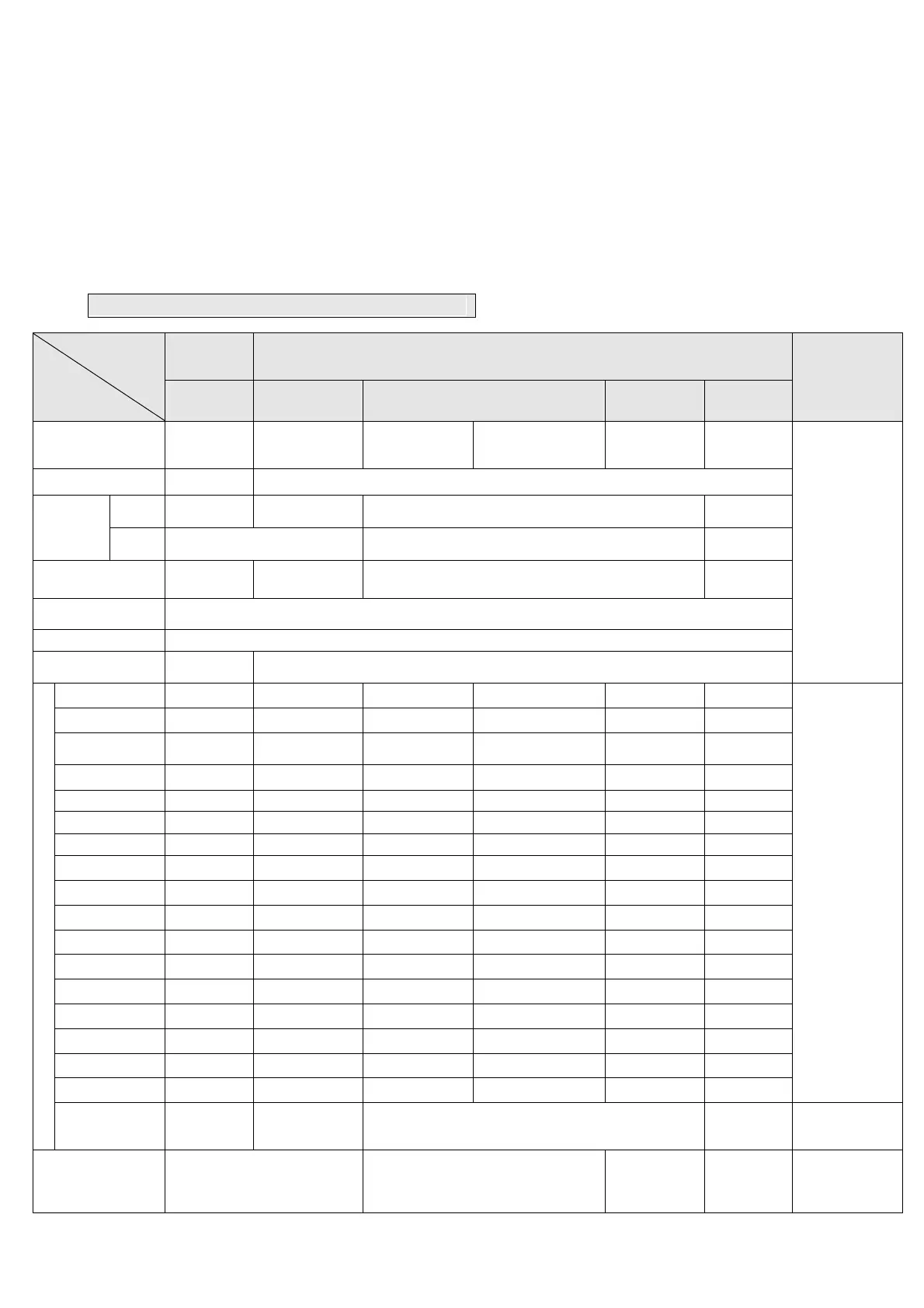
6.1 Specifications of Digital Input (DI) Circuit
Item
Specifications
5VDC
Differential
Input
24VDC Single-end Input
Note
Ultra High
Speed(HSC)
High Speed
(HSC)
Medium Speed(HSC) Mid/Low Speed Low Speed
Maximum input
frequency*/
accumulated time
920KHz 200KHz 20KHz (HHSC) Total 5KHz (SHSC) 0.47 mS*
1
4.7 mS
*: Half of
maximum
frequency while
A/B phase input
Input Signal Voltage 5VDC±10% 24VDC±10%
Input
Current
Threshold
ON
Current
>11 mA >8 mA >4mA >2.3mA
OFF
Current
<2 mA <1.5mA <0.9mA
Maximum Input
current
20mA 10.5mA 7.6mA 4.5 mA
Input Status
Indication
Displayed by LED: Lit when “ON”, dark when “OFF”
Isolation Type Photocoupler signal isolation
SINK/SOURCE
Wiring
Independent
Wiring
Via variation of internal common terminal S/S and external common wiring
List of Input Response Speed for Various Models
FBS-20MNR/T/J X0,1 X4, 5, 8, 9 X2,3,6,7,10,11
*
1
:Limit of input
speed in MA
model is
10KHz
FBS-32MNR/T/J X0,1,4,5 X8, 9, 12, 13 X2,3,6,7,10,11,14,15 X16~19
FBS-44MNR/T/J
X0,1,4,5,8,9,
12,13
X2,3,6,7,10,11,14,15 X16~27
FBS-10MCR/T/J X0,1 X4,5 X2,3
FBS-14MCR/T/J X0,1 X4,5 X2,3,6,7
FBS-20MCR/T/J X0,1,4,5 X8,9 X2,3,6,7,10,11
FBS-24MCR/T/J X0,1,4,5 X8,9.12,13 X2,3,6,7,10,11
FBS-32MCR/T/J X0,1,4,5,8,9 X12,13 X2,3,6,7,10,11,14,15 X16~19
FBS-40MCR/T/J X0,1,4,5,8,9 X12,13 X2,3,6,7,10,11,14,15 X16~23
FBS-60MCR/T/J X0,1,4,5,8,9,12,13 X2,3,6,7,10,11,14,15 X16~35
FBS-10MAR/T/J X0,1,4,5 X2,3
FBS-14MAR/T/J X0,1,4,5 X2,3,6,7
FBS-20MAR/T/J X0,1,4,5,8,9 X2,3,6,7,10,11
FBS-24MAR/T/J X0,1,4,5,8,9,12,13 X2,3,6,7,10,11
FBS-32MAR/T/J X0,1,4,5,8,9,12,13 X2,3,6,7,10,11,14,15 X16~19
FBS-40MAR/T/J X0,1,4,5,8,9,12,13 X2,3,6,7,10,11,14,15 X16~23
FBS-60MAR/T/J X0,1,4,5,8,9,12,13 X2,3,6,7,10,11,14,15 X16~35
Expansion
Unit/Module
R/T/J
All Input
Points
Noise Filtering Time
Constant*
3
DHF(0 ~ 15mS)
+AHF(0.47µs)
DHF(0 ~ 15mS)
+AHF(4.7µs)
DHF(0 ~
15mS)
+AHF(0.47µs)
AHF(4.7ms)
DHF:Digital
Hardware Filter
AHF:Analog
Hardware Filter