Do you have a question about the Faudi AFGUARD and is the answer not in the manual?
| Brand | Faudi |
|---|---|
| Model | AFGUARD |
| Category | Measuring Instruments |
| Language | English |
Specifies the intended purpose and applications of the AFGUARD® sensor for measuring free water in Jet Fuel.
Outlines the requirements for installation, commissioning, and operation by trained technical personnel.
Details the user's responsibility for complying with safety conditions and standards for the sensor.
Provides instructions for returning the device for repair, including cleaning and documentation.
Explains the IP67 protection and the importance of using the correct cable for its maintenance.
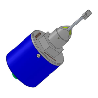
Describes the product structure and the permanently engraved identification markings on the AFGUARD®.
Details the importance of the nameplate's legibility and the information it provides for the AFGUARD®.
Instructions for checking the delivery, handling packaging, and storing the AFGUARD® sensor upon receipt.
Provides dimensions and mounting position requirements for the AFGUARD® sensor installation.
Specifies the physical dimensions of the AFGUARD® sensor for installation planning.
Details the recommended horizontal mounting position and space requirements for the AFGUARD®.
Explains the use of special threads for AFGUARD® installation and the importance of using approved parts.
Guidance on selecting a suitable installation location for easy access and vibration-free mounting.
Recommends specific AFGUARD® orientations in the pipe section for accurate droplet size detection.
Outlines the components required for a complete measuring system, including the sensor and converter.
Details the use of inherently safe isolating converters for signal output in hazardous areas.
Explains how to ensure intrinsic safety when combining AFGUARD® with isolating converters.
Provides minimum directives for installing the optical sensor, emphasizing careful handling and torque.
Demonstrates the steps and considerations for installing the AFGUARD® sensor into a pipe section.
Lists key checks to ensure correct mounting position, torque, and cable arrangement after installation.
Outlines the steps to safely dismantle the AFGUARD® sensor, reversing installation procedures.
Details the recommended wiring method for connecting the AFGUARD® to an isolated converter.
Describes the principle of operation, explaining how the sensor detects free water using IR light.
Explains the 4-20 mA signal output and its interpretation for different states like self-check or water slug.
Recommends calibration checks and specifies the factory calibration range for the AFGUARD®.
Provides a procedure to check the installation and functionality by connecting a current meter.
Provides guidance on cleaning the sensor's optical surfaces to maintain performance.
Details the firmware requirements and how to check the current version for compliance.
Describes the CCS for processing contamination data, relaying alarms, and logging data.
Details the 1-channel Ex barrier for signal transmission between hazardous and safe areas.
An indicator light for warning and alarm situations related to critical free water levels.
A device for periodically testing the AFGUARD® installation loop according to JIG requirements.
A specialized tool for correctly applying the recommended torque of 50 Nm during sensor installation.
An accessory for resetting alarm levels on the Contamination Control System.
Includes optional items like torque wrenches, welding sleeves, and spare gaskets for installation.
Refers users to Chapter 14 for detailed troubleshooting guidance on issues and solutions.
Provides a caution and indicates that only authorized personnel should perform sensor checks.
Lists available spare parts such as sealing, cable, hard case, and protection sleeve.
Instructions for returning the device for repair, emphasizing cleaning and the Declaration of Decontamination.
Guidance on disposing of electronic components in accordance with local regulations.
Specifies the measured values and the measuring range for the AFGUARD® sensor.
Lists the operating and storage temperature, humidity, and ingress protection rating.
Details electrical parameters for the supply circuit and optical radiation specifications.
Specifies operating pressure, process temperature, and process medium compatibility.
Provides information on design, dimensions, weight, and hazardous area approval.
Presents reliability data, including MTTF (Mean Time To Failure) calculations.
References the availability of the Failure Mode and Effects Analysis (FMEA) report.
Provides an English translation of the EC-Type Examination Certificate for the AFGUARD® sensor.
Documents the approval of the AFGUARD® for use in Zone 1 hazardous areas in India by PESO.
Indicates that the EC Declaration of Conformity is available upon request.