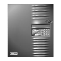
1.3 Control and Indicators
1.3.1 Switch Controls
• Alarm Acknowledge
• Trouble Acknowledge
• Signal Silence
• System Reset/Lamp test
• Programming buttons
– Menu/Back
– Back Space/Edit
– OK
• 12 button keypad
1.3.2 LED Indicators
• AC Power On (green)
• Alarm (red)
• Supervisory (yellow)
• System Trouble (yellow)
• Power Fault (yellow)
1.3.3 Audible Sounder
An Alarm/Trouble sounder is located on the Basic System Module (BSM)
1.4 Optional Modules
The following optional modules and
features are available:
1.4.1 Digital Communicator (DACT)
The Model 7100-D provides an integral digital communicator (DACT), fully programmable from the keypad,
which is compatible with Digital Alarm Receivers (DACRs) that can receive the following formats:
SIA DC8
SIA DCS20
Ademco Contact ID
3+1 1400 Hz
3+1 2300 Hz
4+2 1400 Hz
4+2 2300 Hz
1.4.2 Class A Option Module (CAOM)
All 7100 Models are supplied with Class B Notification Appliance Circuits and Class B Signaling Line Circuits.
For Class A operation, the addition of a CAOM Module is required. This module operates with all 7100 Models
and enables the signaling line circuits to operate as Class A, Style 6 or 7 and notification appliance circuits to
operate as Class A, Style Z. It supplies the additional terminals for these circuits.
1.4.3 Municipal Circuit Option Module (MCOM)
The MCOM Module can trip a Local Energy City Master Box, operate in reverse polarity mode for leased line
connection, or energize a solenoid for releasing service.
• Ground Fault (yellow)
• NAC 1Silenced (yellow)
• NAC 2 Silenced (yellow)
• System Silenced (yellow)
10 of 43 9000-0447
Technical Manuals Online! - http://www.tech-man.com
 Loading...