ST100 Series HART
2 Fluid Components International LLC
Installation
General
For details on the general mounting, placement of sensor head and mounting options see the Basic User Manual, 06EN003400.
Electrical Wiring
Access the wiring terminal block by removing the rear electrical connection cover. This cover can be locked closed by the cover locking screw.
Release the cover locking screw and remove the cover.
Cable access to wiring connections is obtained through one of the four conduit outlets, see Figure 6 below.
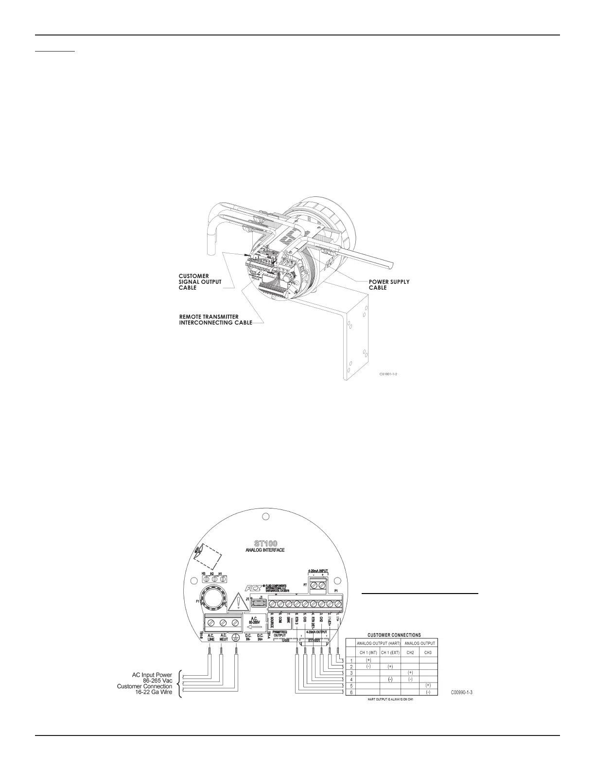
Figure 1 - HART Output Wiring Table
The HART connections for the ST100 are located in the back panel. The connector for the HART is P1A; the pins are labeled “CH1” and “RTN 1/2”.
The ST100 HART connections are non- polarized, but polarity needs to be observed for other manufacturer’s devices. Connect the HART bus cable as
noted below. See Appendix A for Channel 1 HART Connections on instruments shippped before April 2012.
Figure 6 - Instrument Wiring
See Appendix A for Channel 1 HART
Connections on instruments shippped
before April 2012.

 Loading...


