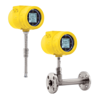
ST100 Series Probus PA
Installation
General
For details on the general mounting, placement of sensor head, and mounting options see the Basic User Manual.
Electrical Wiring
Access the wiring terminal block by removing the rear Electrical Connection Cover. This cover can be locked closed by the cover locking screw.
Release the cover locking screw and remove the cover.
Cable access to wiring connections is obtained thru one of the conduit ports.
FCI recommends the use of PROFIBUS PA and FOUNDATION Fieldbus-H1 cable compliant with the “H1 Cable Test Specification FF-844”
Figure 1
C01109-1-1
PA+
PA -
JUMPERS SET
OUTPUT CUSTOMER CONNECTION
PROFIBUS LINE A (+)
PROFIBUS LINE B (-)
PROFIBUS GND
The PROFIBUS PA connections for the ST100 are located in
the back panel. The connector pins are labeled “A(+) Pin #2”
and “B(-) Pin #3”. The ST100 PROFIBUS PA connections are
non-polarized, but polarity needs to be observed for other
manufacture’s devices. Connect the Field bus cable as noted
below.
In addition to the PROFIBUS PA connections in the back
panel, the ST100 also has a series of jumpers used to select
other digital communication protocol. Confirm that FF+/PA+
and FF-/PA- have the shorting jumper installed, this select
the output pins for the PROFIBUS PA digital protocol.
Topology and Network Configuration
The ST100 supports both Bus topology and Tree topology. Both types have a trunk cable with two terminations. The devices are connected to the
trunk via spurs. The spurs may be integrated in the device giving zero spur length. A spur may connect more than one device, depending on the
length. Active couplers may be used to extend spur lengths.
Active repeaters may be used to extend the trunk length.
The total cable length, including spurs, between any two devices in the Fieldbus should not exceed 1900m. The connection of couplers should be
kept less than 15 per 250m.
PLC
PROFIBUS DP
DP/PA SEGMENT
COUPLER
PROFIBUS PA
DISTRIBUTER
TERMINATION
BUS RESISTOR
ST100 ST100 ST100 ST100 ST100
Fluid Components International LLC 2

 Loading...


