10
17. Another feature of the Master-Slave and / or
Alternating Circuit congurations is the ability to
have a Slave take command for product delivery
if one of the following alarm conditions is present
with the Master:
• Underload (Tank Empty)
• Low Incoming Voltage
• Locked Rotor in PMA
• High Temperature in EcoVFC
• Over Speed
SW6 pole 2 (This option only needs to be
selected on the Master controller)
ON an alarm condition on any controller will shutdown
all controllers. Required setting for VR PLLD.
OFF an alarm condition will shutdown only the
controller with the alarm. (factory setting)
When this option is selected, switch ON, the entire system
will shutdown if any of the controllers, Master or Slaves,
alarms. The system will not run until the alarm is corrected
and the reset button is pushed or the Fault Shutdown
option switch is turned OFF and the reset button is pushed.
18. Wire the RS485, connecting the master EcoVFC
to the slave(s) EcoVFC as shown in Figure 5. Wire
per NFPA 30A, and NFPA 70. For the signal wires,
use at least 0.326 mm
2
(22 AWG) (600V minimum)
4 conductor shielded cable with a drain and within
a common jacket. Cut wires to length so that
there is no excess wiring touching circuit board
components.
Note: When wiring a Master - Slave and / or Alternating
Circuit set, connect the signal from the dispenser
(hook) to the terminals of the Master EcoVFC only.
The Master controller will energize the Slave(s)
when needed without a signal from the dispenser.
19. When all connections are complete, reinstall the
EcoVFC covers and activate supply power. Verify
that the front panel status indicator is displaying Id
(Idle) for both Master and Slave(s)
No
te:
When working with a Master-Slave or Master-Slave/
Alternating Circuit conguration, there can be one
Master and up to (31) slaves. When connected properly,
the yellow Communication LED will ash quickly on the
Master unit and ash in sequence through the Slave
unit(s). See Figure 2 for LED location.
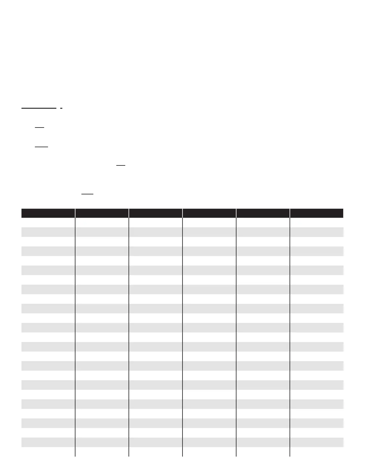
Table 1 – Native EcoVFC Communication Addressing: SW2 (see Figure 2 for location of switch)
Address Pole 1 Pole 2 Pole 3 Pole 4 Pole 5
Master Off Off Off Off Off
Slave - 1 On Off Off Off Off
Slave - 2 Off On Off Off Off
Slave - 3 On On Off Off Off
Slave - 4 Off Off On Off Off
Slave - 5 On Off On Off Off
Slave - 6 Off On On Off Off
Slave - 7 On On On Off Off
Slave - 8 Off Off Off On Off
Slave - 9 On Off Off On Off
Slave - 10 Off On Off On Off
Slave - 11 On On Off On Off
Slave - 12 Off Off On On Off
Slave - 13 On Off On On Off
Slave - 14 Off On On On Off
Slave - 15 On On On On Off
Slave - 16 Off Off Off Off On
Slave - 17 On Off Off Off On
Slave - 18 Off On Off Off On
Slave - 19 On On Off Off On
Slave - 20 Off Off On Off On
Slave - 21 On Off On Off On
Slave - 22 Off On On Off On
Slave - 23 On On On Off On
Slave - 24 Off Off Off On On