9
For Alternating Circuit Conguration (not
applicable to IST-VFC Mode)
Set Master SW3 Pole 3 to OFF, SW3 Pole 8
to ON and SW2 switches all OFF
For Slave(s), SW3 Pole 3 is set OFF (factory
default), SW3 Pole 8 to OFF and SW2 switches
per Table 1.
For Master – Slave and Alternating Circuit
Conguration (not applicable to IST-VFC Mode)
Set Master SW3 pole 3 and SW3 Pole 8 are
ON and SW2 switches all OFF
For Slave(s), SW3 Pole 3 and SW3 Pole 8 are
OFF and SW2 switches per Table 1
Note: For IST-VFC Compatibility Mode (SW6 Pole 3 ON),
set Master SW3 pole 3 ON, set Slaves(s) SW3
pole 3 OFF, and set SW2 switches per Table 1A.
Line leak detection performance can be
affected when using multiple EcoVFCs.
FE Petro does not recommend using
the Alternating Circuit feature in
conjunction with electronic line leak
detection. Some electronic line leak
detector manufacturers require that
the Master turn on rst all of the time.
Please refer to the manufacturer’s
requirements.
Caution
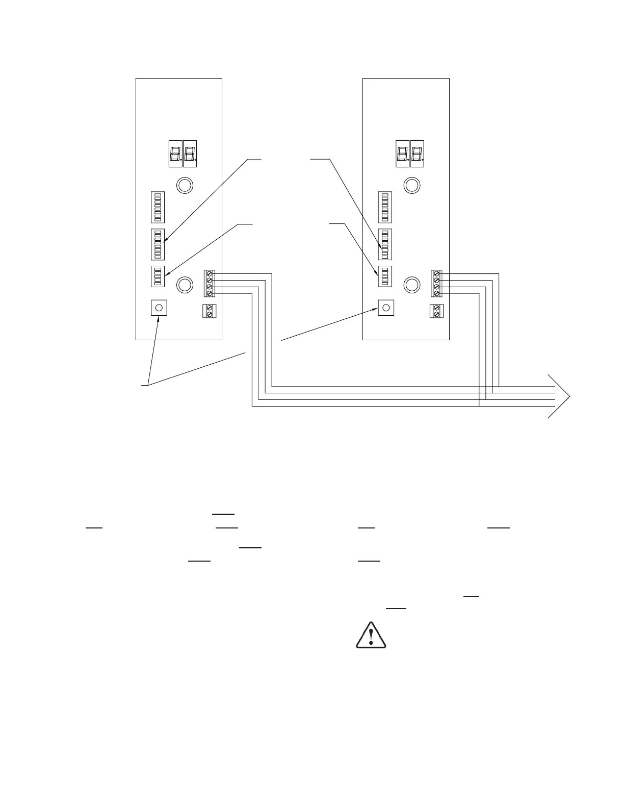
RS485 wiring for Master/Slave and Alternating congurations
per table 1
serial address (SW2)
Set all switches of
SW3 poles 4&5 on
master and slave(s)
must match
Set Pressure
Select (SW1) to
same position for
all units
SW2
SW3
312 4
SW6
MASTER
SW2
SW3
312 4
Additional Slave(s)
Connections
SW6
SLAVE
Figure 5: Setup Master / Slave Conguration