Do you have a question about the FE PETRO EcoVFC and is the answer not in the manual?
Connects dispenser signal for pump activation.
Connects submersible pump motor control wires.
Connects the main power supply to the EcoVFC.
Details electrical input and output requirements for the controller.
Outlines operating temperature, humidity, and altitude limits.
Shows operational codes and status indicators.
Covers reset, alarm silence, and communication LEDs.
Explains the function of SW1, SW2, SW3, and SW6 switches.
Proper connection of conduit, grounding wire, and seal.
Table for maximum wire runs based on gauge.
Default switch configurations for common setups.
Settings for leak detection, product type, master/slave, and motor selection.
Settings for alarm control, IST-VFC compatibility, and alternating circuits.
Explains Master-Slave, Alternating, and combined modes.
Configuration for rotating pump operation.
Assigning unique addresses for network communication.
SW2 settings for IST-VFC compatibility.
SW3 and SW6 settings for timed alternating pumps.
Table mapping addresses to timed run durations.
Setting the rotary switch (SW1) for initial pressure.
Adjusting SW3 poles 4 & 5 for piping effects.
Defines codes like Id, xx:yy, Pr:NN, PL, Sr.
Troubleshooting UL and LI error codes.
Troubleshooting LU, Er, SU, and rl error codes.
Troubleshooting OS and OC error codes.
Troubleshooting SC, HO, and Lr error codes.
Shows connections for VS2 and VS4 in stand-alone mode.
Diagram for connecting EcoVFC in master/slave setup.
Diagram for alternating circuit configurations.
Diagram for combined master/slave and alternating setups.
Wiring for replacing an IST-VFC slave with an EcoVFC.
Wiring for replacing an IST-VFC master with an EcoVFC.
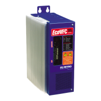
The EcoVFC (Eco Variable Frequency Controller) is a device designed to manage the operation of submersible pumps in fueling systems, specifically for volatile hydrocarbon liquids like gasoline and diesel fuel. It functions as a variable frequency controller, optimizing pump performance and ensuring efficient product delivery.
The EcoVFC's primary function is to regulate the speed of submersible pump motors, such as the FE Petro PMA models VS2 and VS4, by adjusting the frequency of the electrical power supplied to them. This variable frequency control allows the pump to operate at different speeds, matching the demand for fuel and maintaining a consistent pressure in the piping system. This contrasts with traditional fixed-speed pumps that run at full capacity regardless of demand, potentially leading to energy waste and increased wear.
The controller receives a voltage signal from dispensers, which indicates when a pump needs to turn on. Based on this signal and other operational parameters, the EcoVFC intelligently controls the pump motor. It is designed to accommodate both single and multiple pump configurations, including Master/Slave setups and Alternating Circuit configurations, where multiple controllers work together to manage fuel delivery and tank levels.
In a Master/Slave configuration, a master EcoVFC controls the primary pump and can activate slave controllers to bring additional pumps online when demand increases. This ensures adequate product flow during peak times. The Alternating Circuit configuration allows controllers to rotate as the primary pump, helping to balance wear across multiple units and manage tank levels, especially at busy sites. A proportional alternating circuit feature further refines this by allowing each controller to run for a set time proportional to the tank size it serves before alternating.
The EcoVFC also incorporates several safety and diagnostic features. It continuously monitors various operating parameters and can detect fault conditions, displaying alarm codes on its front panel. These codes help service personnel quickly identify and troubleshoot issues such as underload (empty tank), low incoming voltage, locked rotor faults, open circuits, short circuits, high temperature, and over speed.
The EcoVFC is designed for installation in a non-hazardous indoor location, with specific environmental requirements for temperature and humidity. Its user interface panel, located under the front cover, provides visual feedback on the controller's status and allows for configuration adjustments.
The "Pump Status Display" shows codes indicating the controller or pump status, such as "Id" for idle, "xx:yy" for software revision, "Pr: NN" for pressure regulation, "PL" for power limit, and "Sr" for slave running. These codes provide a quick overview of the system's operational state.
Configuration switches (SW1, SW2, SW3, SW6) on the user interface panel allow installers and service personnel to set various operational parameters. SW1, the "Operational Pressure Switch," adjusts the submersible pump's operating pressure. SW2, the "Address Switch," is used for Master/Slave configurations and Turbine Pump Interface (TPI) communication, allowing unique addresses to be assigned to each controller in a multi-pump setup. SW3 and SW6 are "Configuration Switches" that enable settings for different product types (gasoline or diesel), pump motor horsepower (VS2 or VS4), leak detection systems, automatic fault resets, and Master/Slave/Alternating Circuit operational modes.
The device includes a "Silence Alarm/Fault Readout Button" to turn off audible alarms and display the last three fault conditions encountered. A "Reset Button" allows for clearing any fault conditions. For Master/Slave configurations, an RS485 connection facilitates communication between controllers, and a "Communication LED" indicates activity.
The EcoVFC incorporates several features to aid in maintenance and troubleshooting. The diagnostic display and alarm codes are crucial for quickly identifying system issues. The "Silence Alarm/Fault Readout Button" and "Reset Button" are direct tools for managing alarms and clearing faults, allowing for immediate response to operational anomalies.
The manual provides detailed troubleshooting steps for each alarm code, guiding service personnel through a systematic process of diagnosis and repair. This includes instructions for checking electrical connections, verifying switch settings, inspecting pump components, and performing flow rate tests. For example, if an "UL" (Underload) fault occurs, the manual suggests checking fuel levels, verifying SW3 Pole 6 settings (for pump horsepower), and inspecting the PMA inlet for obstructions.
Safety precautions are heavily emphasized throughout the manual, particularly regarding electrical work. Instructions include always tagging and locking circuit breakers before servicing, waiting a specified time after disconnecting power to allow capacitors to discharge, and ensuring proper grounding. These measures are critical for preventing electrical shock, fire, or explosion.
The EcoVFC's design also considers ease of access for servicing. The front panel can be removed to access the user interface board and internal components. The modular nature of some components, such as the fan assembly and user interface board, suggests that these parts can be replaced if they fail. The manual also provides guidance on wiring connections, including recommended wire sizes and maximum run lengths, which are important for maintaining optimal performance and preventing issues like false fault indications due to long or undersized wiring.
| Category | Controller |
|---|---|
| Manufacturer | FE PETRO |
| Model | EcoVFC |
| Display | LCD |
| Communication | RS-232, RS-485 |
| Enclosure Rating | NEMA 4X |