4
User Interface Panel Is the Front Panel Located Under the EcoVFC Cover
(Factory default switch settings shown)
Pump Status
Display
Nylon Screw
SW6
Configuration Switches
SW1
SW1
Operational Pressure Switch
SW2
Address Switches
SW3
Configuration Switches
2
2
8
5
4
3
7
6
1
0
9
SW2
O
N
1 4
3
5
SW3
O
N
2
1
4
3
5
6
SW6
7
8
4
O
N
1
3
2
6
5
78
Resistive: 5A @ 250VAC or 30VDC
Inductive: 2A @ 250VAC or 30VDC
Closed when submersible pump is running
Normally Open Relay Contact
RS 485 connection
Reset Button
Frequency (F)
2314
Ground (G)
+
-
Silence Alarm/Fault Readout
Button
Communication LED
(N.O. relay sold separately, P/N 228289930)
Nylon Screw
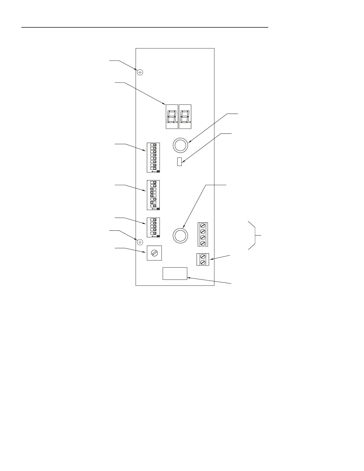
Figure 2: EcoVFC Front Switch Panel
Pump
Status Display: Displays codes that indicate controller or pump status, see the Troubleshooting section
for details of codes.
Silence Alarm/Fault Readout button: Push and it will turn off audible alarm, Push and hold button and the
Pump status display will show the last 3 fault conditions the EcoVFC
encountered.
Reset Button: Resets controller of any fault condition
Communications LED: Used in Master/Slave type congurations to indicate communication activity
RS485 connection: Used in Master/Slave congurations (Frequency connection not used in IST-VFC Mode)
Relay contact: Normally open, the relay closes when the pump is running (relay sold separately).
SW1 Operational Pressure Switch: Adjusts the submersible pump’s operation pressure
SW2 Address Switch: Used in Master/Slave and Turbine Pump Interface (TPI)
Note: TPI is a feature on the TS5 series consoles which allows tank gauge and pump controller communication.
SW3 Conguration switches: Factory Default settings for Stand alone use in Gasoline. See Options Select
Section for other settings.
SW6 Conguration Switch: More conguration options, see Options Select Section for specic settings
Nylon Screw: (P / N 223561102) Attaches the user interface board to the eld wire panel heatsink, required for
high-voltage isolation. Use only factory-supplied parts.