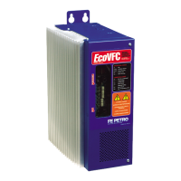
7
Optional Select Switch Settings
10. To make changes to the conguration switches
SW3 and SW6 (See Figure 4), make sure power
supply is locked and tagged out, then remove
the two screws from the plastic shield covering
the User interface board. Set all DIP switches as
desired per the details below.
SW3 Pole 1
ON for Mechanical Leak Detectors (factory
setting)
OFF For Some Electronic Line Leak Detection
systems. Required setting for Veeder Root PLLD.
SW3 Pole 2
ON for Gasoline (factory setting)
OFF for Diesel product
Note: Because gasoline has a different specic gravity
than diesel fuel, the correct setting of Pole 2 is
important to ensure that the EcoVFC regulates
pressure at the desired level.
SW3 Pole 3
ON for Master controller (See Master Slave
Control Connections for details)
OFF for Stand-alone operation or Slave
conguration (factory setting)
SW3 Poles 4 and 5 (Pipe Compensation)
See Calibration Section of this Manual for
details in setting these switches (default is ON,
ON)
SW3 Pole 6
ON when using PMAVS4 motor
OFF when using PMAVS2 motor (factory
setting)
Note: Incorrect setting can cause the EcoVFC to
give false indications of SC (short circuit) or
UL (underload). Set SW3 Pole 6 properly to
horsepower of pump connected.
SW3 Pole 7
ON for Automatic reset of “Under Load” fault.
An empty tank will cause an Under load fault.
The EcoVFC will automatically reset when the
condition is corrected.
OFF must push Reset button to clear the
“Under Load” fault (factory setting)
Note: Not functional in IST-VFC Compatibility Mode,
leave in OFF position.
SW3 Pole 8 (for multiple EcoVFC controllers
working together)
See Alternating Circuit Control section for
details (default is OFF)
Note: Not functional in IST-VFC Compatibility Mode, set
with SW2 Pole 5 per Table 1A.
SW6 Pole 1
See Troubleshooting section for details of the Extended
Run Alarm
ON Will disable the Extended Run Alarm
condition
OFF The Extended Run Alarm is active
(factory setting)
Note: Not functional in IST-VFC Compatibility Mode,
leave in OFF position.
SW6 Pole 2 (For Master-Slave and Alternating
Circuit congurations ONLY)
See Master-Slave Fault Shutdown Control
section for details of this switch (default is OFF)
Note: Not functional in IST-VFC Compatibility Mode, set
with SW2 Pole 5 per Table 1A.
SW6 Pole 3
ON for IST-VFC Compatibility Mode, unit will
then ONLY communicate with rev 1.5 software
IST-VFCs in Master-Slave congurations (not
for use in communicating Master-Slave with
other EcoVFCs)
OFF native EcoVFC Master-Slave
communication (factory setting)
Note: Available in EcoVFC software versions 1.18 and
higher only.
SW6 Pole 4
(With software version 1.24 or higher)
ON When the alternating circuit conguration is
used this will alternate submersibles every 30
minutes when a hook signal is continuous. This
option is used to assist in keeping tanks balanced
at busy sites.
OFF When Alternating Circuit is not needed.
(See page 11 for additional details)
SW6 Pole 5
ON With software version 1.24 this feature, called
Proportional Alternating Circuit, allows setting the
time each controller runs before it alternates. The
feature this will help manage tank levels but will
not replace a syphon bar or managing levels via
INCON T5 series Automatic tank gauges “leveling”
mode. (See page 12 for a detailed description).
OFF When Proportional Alternating Circuit is not
needed.