21
GND
ORG
RED
BLK
GND
L1
L2
L3
N
1
9
0
Switches located on
user interface panel
SW1
3
4
2
SW2
5
6
7
8
21
5
4
3
SW3
3
2
1 6
54
8
7
SW6
1
43
2
7
6
5
8
Switch
Handle
Dispenser
RETURN
110 VAC or 240 VAC Supply
THERMAL
OVERLOADS
PMAMVS2
CONNECTOR
BLACK
RED
ORANGE
PLUG
O
N
O
N
O
N
Incoming power
3 phase, 50 or 60 Hz
360 -440 VAC
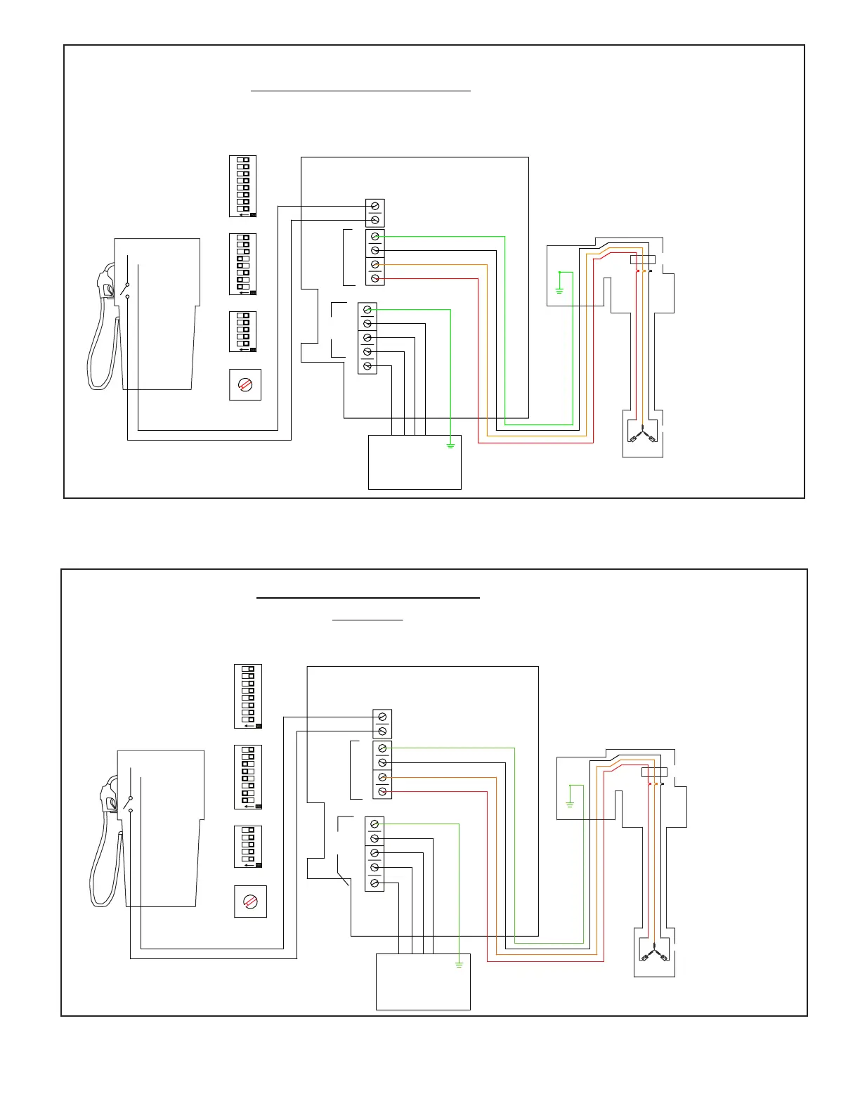
EcoVFC
Field Wire Panel
Wire Diagram for EcoVFC with PMAVS2
Stand Alone
Note: see installation and
owners manual for further
details of switch settings
and EcoVFC calibration
settings of SW1 rotary
position and SW3 poles 4 & 5.
Note: see product installation
instructions for further
details. Wiring must conform
to all federal, state, and
local codes. Control panels
are for non-hazardous, indoor
use only.
TO MOTOR
TO
LINE
GND
ORG
RED
BLK
GND
L1
L2
L3
N
1
9
0
Switches located on
user interface panel
SW1
3
4
2
SW2
5
6
7
8
21
5
4
3
SW3
3
2
1 6
54
8
7
SW6
1
43
2
7
6
5
8
Switch
Handle
Dispenser
RETURN
110 VAC or 240 VAC Supply
THERMAL
OVERLOADS
PMAMVS4
CONNECTOR
BLACK
RED
ORANGE
PLUG
O
N
O
N
O
N
Incoming power
3 phase, 50 or 60 Hz
360 - 440 VAC
EcoVFC
Field Wire Panel
Wire Diagram for EcoVFC with PMAVS4
Stand Alone
Note: see installation and
owners manual for further
details of switch settings
and Ecovfc calibration
settings of SW1 rotary
position and SW3 poles 4 & 5.
Note: see product installation
instructions for further
details. Wiring must conform
to all federal, state, and
local codes. Control panels
are for non-hazardous, indoor
use only.
TO MOTOR
TO
LINE
Figure 7 - Stand Alone conguration of EcoVFC with 2 horsepower variable speed (VS2)
Figure 8 - Stand Alone conguration of EcoVFC with 4 horsepower variable speed (VS4)